
Videos
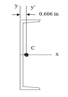
Figure (a) shows the cross-sectional dimensions for the structural steel section known as

Trending nowThis is a popular solution!

Chapter 9 Solutions
International Edition---engineering Mechanics: Statics, 4th Edition


- The cross-sectional area shown is subjected to V = 600 kN and M =1000 kN-m. What is the transverse shear stress just above point B? (in MPa) 100 mm 100 mm 100 mm 100 mm 100 mm B 100 mm A Varrow_forwardEXAMPLE: II. 2 ft Show the V-M diagram using Area Method of the following beam: R₂ 200 lb/ft 4 ft - Hinge 2 ftarrow_forwardThe figure below shows the cross-section of an axisymmetric composite beam that comprises steel (Young's modulus 270 GPa) and aluminum (Young's modulus 90 GPa) sections that are bonded together. The steel section is of wall thickness 15 mm and the aluminum section is of wall thickness 10mm. The steel section comprises 4 axisymmetric holes of 5 mm diameter as shown. Given that the beam is bent by a couple moment of 1200 Nm, determine the maximum stress in steel and aluminum. 4 holes of diameter 5 mm. 12 mm steel aluminumarrow_forward
- A cross-section of a beam is shown in Figure Q2. If the shear force in this section is V 163 KN, determine the value and the location of the maximum shear stress in the section. In Figure Q2, a = 77 mm and the origin of the coordinate system is at centroid of the cross section. y= A Z= a mm; 2a mm; O 4a The vertical coordinate (y-coordinate; the y-axis serves as the axis of symmetry of the cross-section.) and horizontal coordinate (z-coordinate) of the location where the maximum shear stress occurs in the section are Figure Q2 3a a The vertical distance from the location where the maximum shear stress occurs in the section to the bottom side (AB) of the cross section can be calculated as Distance = mmarrow_forwardConsider the figure below. If T1=3,500 lbs and T2 = 2,500lbs, fin the angle alpha made by T2 from the horizontal.arrow_forwardConsider the beam in the picture below: 7kN/m 5kN/m P N/m Section 1 Section 2 Section 3 - L/3 L/3 L/3 %3D Take P = the last four digits of your student number in N/m. If P<250 N/m then take P = 30OON/m instead. Take L = the third digit of your student number, reading left to reight. If this value is zero then take L = 2 Assume: The reaction at the Pin = V pin 47000L+9PL )N 54 The reaction at the Roller = Vroller = 61000L+9PL 54 and that both reactions act vertically upwards. a) Find an expression for the internal moment for Section 1. Show all working and any relevant free body diagrams. b) What is the maximum magnitude of the internal moment for Section 1? Mark sure you prove that the value you calculate is the maximum. c) Find an expression for the internal moment for Section 2. Show all working and any relevant free body diagrams. d) What is the maximum magnitude of the internal moment for Section 2? Mark sure you prove that the value you calculate is the maximum. e) Find an…arrow_forward
- E ME5413 Structural Mechanics - Adobe Reader File Edit View Window Help Оpen 27 41 113% Tools Fill & Sign Comment Parth Mathur - v Export PDF Adobe ExportPDF The cross-section of a beam is as shown in Example Fig. 4.19. If permissible stress is 150N/mm2, find its moment of resistance. Compare it with equivalent section of same area but (a) Square section (b) rectangular section with depth twice the width and (c) a circular section. Convert unlimited PDF files to Word or Excel format. Select PDF File: t WINSEM2020-21_MEE2002_E... 1 file / 1.74 MB Convert To: Microsoft Word (*.docx) Recognize Text in English(U.S.) Change Convert 200mm- View Converted Files • Create PDF • Edit PDF 10mm • Combine PDF • Send Files • Store Files 8mm- 400mm 10mm 11:39 e Type here to search 口 O G ) ENG 16-04-2021 (1arrow_forwardThe bending moment diagram and cross-section for a beam are shown below. Use the elastic flexural formula ox = -Mzy/l, to determine the required strength of the beam to resist the compressive stresses. Circle the correct answer for the compressive strength in ksi: 2.3, 2.5, 27.5, 30, 37.7 Show your work below. Bending Moment Diagram Beam Cross-Section 4" +50 2' (K-Fe) 2" 2" - 40 2"arrow_forwardFor a uniformly loaded span of a cantilever beam attached to a wall at x = 0 with the free end at x = L, the formula for the vertical displacement from y = 0 under the loaded condition with y the coordinate in the direction opposite that of the load can be written as follows: Y= -(X4 – 4X³ + 6X²) where Y is the vertical displacement, X = x/L, and L is the length of the beam. The formula was put into dimensionless form to answer the following question: What is the shape of the deflection curve when the beam is in its loaded condition and how does it compare with its unloaded perfectly horizontal orientation? The answer is provided graphically in Figure Q4. Figure Q4 shows the vertical deflection of a uniformly loaded cantilever beam and its comparison with the unloaded perfectly horizontal orientation. Write a script to get the same figure as Figure Q4 by solving the following question. 1 · Unloaded cantilever beam 0.5 Uniformly loaded beam -0.5 -1E > -1.5 -2- -2.5 -3 -3.5 0.5 1 1.5…arrow_forward
- Use the method of SECTIONS to find the true magnitude and direction in bar HG of the truss shown below in Fig 3.5 -500lb -100lb A 45° -200lb H -100lb 2 B -200lb -200lb MAGNITUDE AND DIRECTION OF SUPPORTS -500lb H -100lb 45° 2¹ C2D 2¹ Fig 3.5. -200lb -100lb LI 2 B 2₁ 2₁ D 2₁ Earrow_forwardA water gate is to be reinforced with three horizontal beams (running to the page). If the water acts on one side only to a depth of h=6m, find the positions of the beams measured from the water surface so that each beam will carry an equal load. Gate is fully covered by water. [²] = 24 R =arrow_forwardThe dimensions are of the graph are d1 = 7 cm , L1 = 6 m , d2 = 4.2 cm , and L2 = 5 m with applied loads F1 = 130 kN and F2 = 60 kN . The modulus of elasticity is E = 80 GPa . Use the following steps to find the deflection at point D. Point B is halfway between points A and C. What is the reaction force at A? Let a positive reaction force be to the right.arrow_forward
 Elements Of ElectromagneticsMechanical EngineeringISBN:9780190698614Author:Sadiku, Matthew N. O.Publisher:Oxford University Press
 Mechanics of Materials (10th Edition)Mechanical EngineeringISBN:9780134319650Author:Russell C. HibbelerPublisher:PEARSON
 Thermodynamics: An Engineering ApproachMechanical EngineeringISBN:9781259822674Author:Yunus A. Cengel Dr., Michael A. BolesPublisher:McGraw-Hill Education
 Control Systems EngineeringMechanical EngineeringISBN:9781118170519Author:Norman S. NisePublisher:WILEY
 Mechanics of Materials (MindTap Course List)Mechanical EngineeringISBN:9781337093347Author:Barry J. Goodno, James M. GerePublisher:Cengage Learning
 Engineering Mechanics: StaticsMechanical EngineeringISBN:9781118807330Author:James L. Meriam, L. G. Kraige, J. N. BoltonPublisher:WILEY