
Concept explainers
The most economical section using LRFD and ASD.
Answer to Problem 9.1PFS
The safe designed section is
Explanation of Solution
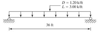
Given Information:
LRFD:
The design load is
The design moment is
Assuming self weight as 0.1 k/ft.
The moment due to self weight is
The total design moment is
The design strength of beam is
Taking
The required section modulus is
Selecting the section such that Z>Zrequired
The plastic section modulus is 283 in.3
ASD:
The design load is
Assuming self weight as 0.1 k/ft.
The total design load is
The design moment is
The design strength of beam is
The required section modulus is
Selecting the section from AISC manual such that Z>Zrequired
Conclusion:
Select
Want to see more full solutions like this?
Chapter 9 Solutions
Structural Steel Design (6th Edition)


- A plate girder must be designed for the conditions shown in Figure P10.7-4. The given loads are factored, and the uniformly distributed load includes a conservative estimate of the girder weight. Lateral support is provided at the ands and at the load points. Use LRFD for that following: a. Select the, flange and web dimensions so that intermediate stiffeners will he required. Use Fy=50 ksi and a total depth of 50 inches. Bearing stiffeners will be used at the ends and at the load points, but do not proportion them. b. Determine the locations of the intermediate stiffeners, but do not proportion them.arrow_forwardb Irom Fig. 9-10 in the text. 9-17. Select the lightest satisfactory W shape section if Fy provided at the ends only. Determine C,. (Ans. W24 × 117 LRFD and ASD) 50 ksi. Lateral bracing is PL = 40 k PL = 40 k D = 1 k/ft U PES %3D 10 ft 10 ft 10 ft FIGURE P9-17 9-18. Repeat Prob. 9-17 if lateral bracing is provided at the concentrated loads as well as at the ends of the span. Determine C,.arrow_forwardDetermine the adequacy of the tension members of the determinate bolted truss shown below based on the service loads shown. Use A50 steel. Assume there are three line of bolts in connection and neglect weight of members. Hint: There are three tension members in the truss.arrow_forward
- The built-up girder below is comprised of four A572 Grade 50 plates welded together. Compute the section modulus (S), plastic modulus (Z₁), and shape factor (Z₁/S). Using Table B41.b of the Specification, determine whether the flanges and web are compact, noncompact, or slender. -PL 1" x 40" 10" CLEAR SPACING PL 1.5" x 20" TYParrow_forwardUse NSCP 2015. The beam shown has continuous lateral support of both flanges. The uniform load consisting of 50% dead load and 50% live load. The dead load includes the weight of the beam. Used grade 50 steel. 6 k/ft |--0-0²- -18'-0"- fo 4-6- -6'-0" 1. Considering LRFD. Which of the following most nearly gives the design load Wu? 2. Considering LRFD. Which of the following most nearly gives the maximum negative design moment, Mu in ft-kips? 3. Considering W12x35 beam section, The section is 4. Considering ASD the W12x35 beam section, Which of the following most nearly gives allowable strength in ft-kipsarrow_forwardA built-up member is used as a column having a length of 20 ft. Assume the member is hinged at the top and at the bottom for buckling in either principal direction. Using A36 steel, determine the axial compressive strength (ASD & LRFD). USE NSCP 2015/ AISC REQUIREMENTS.arrow_forward
- If the beam in Problem 5.5-9 i5 braced at A, B, and C, compute for the unbr Cb aced length AC (same as Cb for unbraced length CB). Do not include the beam weight in the loading. a. Use the unfactored service loads. b. Use factored loads.arrow_forwardFor the Integrated Project (office building), design the Floor Girders in the gravity-only system, assuming that the top flange is fully restrained with the floor diaphragm. 1. Use Table 3-2 from the Steel Manual to select the most economical compact W-shape section. Demands: Stories 1 and 2 Edge: 114.4 k.ft From Table 3-2, use W12x50 D/C = should be less than 0.95: D/C = Stories 1 and 2 Interior: 226.4 k.ft Use W12x50: D/C = Roof Edge: 33.3 k.ft Use W12x40: D/C = Roof Interior: 58.4 k.ft Use W12x40: D/C =arrow_forward5.5-3 A simplrted beam is subjected to a uniform service dead load of 1.0 kip cluding the weight of the beam), a uniform service live load of 0 kipft, and a concentrated service dead load of 40 kips. The beam feet long, and the concentrated load is located 15 feet from the left The beam has continuous lateral support, and A572 Grade 50 steel is used. Is a W30 x 108 adequate a. Use LRFD. b. Use ASD.arrow_forward
- PLATE #3 PROBLEM: A built up section of A992 steel is made from plates fully welded together. The flanges consist of PL16x380 and PL12x500 for the web. Check the beam for flexure. Total load Deflection is limited to L/240. Cite all applicable specifications you used to solve the problem from NSCP 2015. 1. For full lateral support 2. For Lateral bracing at supports and midspan of AB. WD 3. For lateral bracing at supports only, what maximum w and w₁ can the beam carry for WL A WD = 26 kN/m_Includes self wt. WL = 40 kN/m B 10m ee m 2m PL16x380 PL12x500 X = 1.5.arrow_forwardP.Pn Determine the LRFD design strength, P/2c for and the ASD allowable strength,' n' each of the compression members shown. Use the AISC Specification and a steel with F y = 50 ksi, except for Problem 5-8, Fy = 46 ksi. %3D (Ans. 212 k LRFD; 141 k ASD) W8 × 31 20 ft 0 in FIGURE P5-5arrow_forwardThe truss shown is composed of steel sections. If the 2L150 x 90 x 8 A36 steel section was used in member CG, is it satisfactory? Use 2 lines of 4-20mm fasteners spaced 75 mm on center for all joints. The loads applied in the truss are. service loads. Use ASD only. You can use ASEP Manual. Multiply the loads by 10. 50 kN 30 kN- 3 m G 3 m 3 m 30 kN- D 30 kN- A m E H m Carrow_forward
 Steel Design (Activate Learning with these NEW ti...Civil EngineeringISBN:9781337094740Author:Segui, William T.Publisher:Cengage Learning