
Concept explainers
Videos
For the beam and loading shown, determine (a) the slope at point B, (b) the deflection at point D. Use E = 200 GPa.
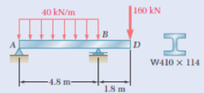
Fig. P9.128
The magnitude
Answer to Problem 146P
The magnitude
Explanation of Solution
Given information:
The section of the beam is
The young’s modulus of steel is
Calculation:
Show the free body diagram of the beam as in Figure 1.
Calculate the vertical reaction at point A by taking moment about point B.
Refer Appendix C “Properties of rolled steel shape (SI units)” for moment of inertia of section
Calculate the value (EI):
Substitute
Calculate the moment due to the reaction at A:
Substitute
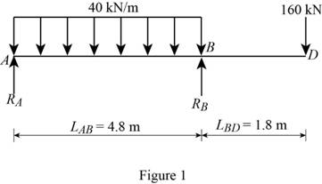
Calculate the
Substitute
Show the
Calculate the area
Substitute
Calculate the moment due UDL:
Substitute
Calculate the
Substitute
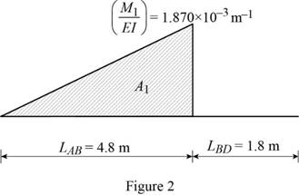
Show the
Calculate the area
Substitute
Calculate the moment due to the point load at D as below:
Substitute
Calculate the
Substitute
Show the
Calculate the area
Substitute
Calculate the tangential deviation of B with respect to A using the relation:
Substitute
Calculate the slope
Substitute
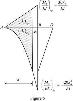
Let point K is the maximum deflection.
Calculate the moment due to the reaction at A as below:
Substitute
Calculate the
Substitute
Calculate the moment due UDL:
Calculate the
Substitute
Show the
Calculate the area
Substitute
Calculate the area
Substitute
Calculate the slope
Substitute
Differentiate the Equation (1).
Solve the value
Iteration 1:
Substitute 3 for
Substitute 3 for
Iteration 2:
Calculate the value
Substitute 3 for
Similarly calculate the value
| f | ||
| 3 | 28.08 | -72 |
| 3.39 | -6.78 | -107.8 |
| 3.327 | -0.188 | -101.6 |
| 3.3251 | 0.005 | -101.42 |
| 3.32514 | 0.0001 |
The value of
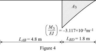
Calculate the slope at the end A related to the point K
Substitute
Calculate the magnitude
Substitute
Thus, the magnitude
Want to see more full solutions like this?
Chapter 9 Solutions
Mechanics of Materials, 7th Edition


- PROBLEM 9.9 Knowing that beam AB is a W130× 23.8 rolled shape and that L P=50 kN, L=1.25 m, and E = 200 GPa, determine (a) the slope at A, (b) the deflection at C. L/2 L/2 [x=0, y=0] [x = L, y=0] L dy 2' dx e = 2.77x10³ rad Yc = 1.156 mm.arrow_forwardPROBLEM 9.15 Mg = 60 kN m For the beam and loading shown, determine the deflection at point C. Use E = 200 GPa. W200 x 35.9 a = 1.2 m -L =4.8 m Yc = = 6.28 mm Tarrow_forwardProblem 5.2 Determine the deflection at x=1m and x=4m. Specify the slope at A and the maximum deflection. El is constant. A -2 m X 6 kN 6 m C 6 kN 6 m 2 m Barrow_forward
- PROBLEM 9.11 Mg (a) Determine the location and magnitude of the maximum deflection of * beam AB. (b) Assuming that beam AB is a W360 x 64, L = 3.5 m, and E = 200 GPa, calculate the maximum allowable value of the applied moment M, if the maximum deflection is not to exceed 1 mm. B = 45.3 kN · marrow_forward9.11 For the cantilever beam shown, determine the slope and deflection at (a) point B, (b) point C. Use E = 29 × 106 psi. w = 600 lb/ft A -6 ft- Fig. P9.11 B 1200 lb --+-3A- H W 8x 15arrow_forwardPROBLEM 9.11 Mo (a) Determine the location and magnitude of the maximum deflection of beam AB. (b) Assuming that beam AB is a W360 x 64, L = 3.5 m, and E = 200 GPa, calculate the maximum allowable value of the applied moment Mo if the maximum deflection is not to excecd I mm. Mo = 45.3 kN · m %3Darrow_forward
- For the cantilever beam and loading shown, determine the slope and deflection at point B. Use E = 27 × 106 15 1b/in. -30 in. The slope at end Bis B 125 lb 10 in. The deflection at end Bis 1.75 in. H X 10 rad. in. ↓ psi.arrow_forwardb. Determine the deflection of the beam at midpoint for the beam loading system shown in the figure given below : Take : E = 200 GN/m2 and I = 83 x 106 m. 20 N 30 N 10 N/m 10 m 5 m 10 m Fig. 10.arrow_forwardFor the beam and loading shown, determine (a) the slope at point B, (b) the deflection at point D. Use E-200 Gpa , I= 462 (10)-6 A 40 kN/m -4.8 m- B 1.8 m 160 kN Darrow_forward
- The two beams shown have the same cross section and are joined by a hinge at C. For the loading shown, determine (a) the slope at point A, (b) the deflection at point B. Use E=29 *106 psiarrow_forwardb. Determine the deflection of the beam at midpoint for the beam loading system shown in the figure given below : Take : E = 200 GN/m? and I = 83 x 106 m4. 20 N 30 N 10 N/m 10 m 5 m 10 m Fig. 10.arrow_forwardDetermine (i) the maximum deflection of the beam (ii) the location of maximum deflection Where; L = 1 P = 33N | = 3.3 x 108 mm4 E = 200 GPaarrow_forward
 Elements Of ElectromagneticsMechanical EngineeringISBN:9780190698614Author:Sadiku, Matthew N. O.Publisher:Oxford University Press
 Mechanics of Materials (10th Edition)Mechanical EngineeringISBN:9780134319650Author:Russell C. HibbelerPublisher:PEARSON
 Thermodynamics: An Engineering ApproachMechanical EngineeringISBN:9781259822674Author:Yunus A. Cengel Dr., Michael A. BolesPublisher:McGraw-Hill Education
 Control Systems EngineeringMechanical EngineeringISBN:9781118170519Author:Norman S. NisePublisher:WILEY
 Mechanics of Materials (MindTap Course List)Mechanical EngineeringISBN:9781337093347Author:Barry J. Goodno, James M. GerePublisher:Cengage Learning
 Engineering Mechanics: StaticsMechanical EngineeringISBN:9781118807330Author:James L. Meriam, L. G. Kraige, J. N. BoltonPublisher:WILEY