
Concept explainers
Videos
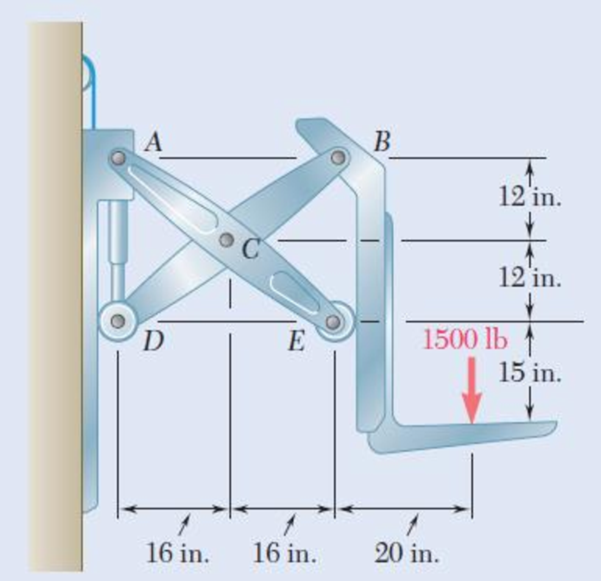
Two identical linkage-and-hydraulic-cylinder systems control the position of the forks of a fork-lift truck. The load supported by the one system shown is 1500 lb. Knowing that the thickness of member BD is
Fig. P1.28

Trending nowThis is a popular solution!

Chapter 1 Solutions
Mechanics of Materials, 7th Edition
Additional Engineering Textbook Solutions
Foundations of Materials Science and Engineering
Fundamentals Of Thermodynamics
INTERNATIONAL EDITION---Engineering Mechanics: Statics, 14th edition (SI unit)
Vector Mechanics for Engineers: Dynamics
Machine Tool Practices (10th Edition)
Applied Statics and Strength of Materials (6th Edition)


- An annular washer distributes the load P applied to a steel rod to a timber support. The rod's diameter is 22 mm, and the washer's inner diameter is 25 mm, which is larger than the hole's permissible outer diameter. Knowing that the axial normal stress in the steel rod is 35 MPa and the average bearing stress between the washer and the timber must not exceed 5 MPa, examine the smallest allowed outer diameter, d, of the washer. %3D %3D +22 mm P Figure 4arrow_forward19. knowing that a force P of magnitude 75 N is applied to the pedestal shown, determine (a) the diameter of the pin at C for which the average shearing stress in the pin is 40 MPa, (b) the corresponding bearing stress in the pedestal at C, (c) the corresponding bearing stress in each support bracket at C. 75 mm 9 mm - 300 mm- B 125 mm D 5 mmarrow_forwardа) An annular washer distributes the load P applied to a steel rod to a timber support. The rod's diameter is 22 mm, and the washer's inner diameter is 25 mm, which is larger than the hole's permissible outer diameter. Knowing that the axial normal stress in the steel rod is 35 MPa and the average bearing stress between the washer and the timber must not exceed 5 MPa, examine the smallest allowed outer diameter, d, of the washer. - 22 mm Figure 4arrow_forward
- 7. Knowing that 0=40° and P=9 kN, determine (a) the smallest allowable diameter of the pin at Bif the average shearing stress in the pin is not exceed 120 MPa, (b) the corresponding average bearing stress in the member AB at B, (c) the corresponding average bearing stress in each of the support brackets at B. P 16 mm 750 mm 750 mm 50 mm- 12 inmarrow_forwardIn the structure shown, an 8 mm diameter pin is used at A, and 12 mm diameter pins are used at B and D. Knowing that the allowable shearing stress is 120 MPa at all connections and that the allowable normal stress and bearing stress is 240 MPa in each of the two links joining B and D, determine the allowable load Parrow_forwardPROBLEM 8.40 A thin strap is wrapped around a solid rod of radius c= 20 mm as shown. Knowing that I = 100 mm and F = 5 kN, determine the normal and shearing stresses at (a) point H, (b) point K. o = 79.6 MPa T=7.96 MPa O =0 T=13.26 MPaarrow_forward
- THE FRAME SHOWN CONSISTS OF FOUR WOODEN MEMBERS, ABC, DEF,BE, AND CF. KNOWING THAT EACH MEMBER HAS A 50X100MM RECTANGULAR CROSS SECTION AND THAT EACH PIN HAS A 13 MM DIAMETER, DETERMINE THE MAXIMUM VALUE OF THE AVERAGE NORMAL STRESS (A) INMEMBER BE, (B) IN MEMBER CF. 1.125 mm 750 mm V2.160 N 100 mm 100 mm 1.000 mm 375 mm 750 mmarrow_forward15. In the steel structure shown, a 6-mm-diamter pin is used at C and 10-mm-diameter pins are used at B and D. The ultimate shearing stress is 150 MPa at all connections, and the ultimate normal stress is 400 MPa in link BD. Knowing that a factor of safety is 3.0 is desired, determine the largest load P that can be applied at A. Note that link BD is not reinforced around the pin holes. Front view 18 mm 6 mm 120 mm- Side view 160 mm Top viewarrow_forwardIn the structure shown, an 8-mm diameter pin is used at A, and 12- mm diameter pins are used at B and D. Knowing that the ultimate shearing stresses is 100 MPa at all connections and that the ultimate normal stress is 250 MPa in each of the two links joining B and D, determine the allowable load P if an overall factor of safety of 3.0 is desired.arrow_forward
- Link AC is made of a steel with a 65-ksi ultimate normal stress and has a xin. uniform rectangular cross section. It is connected to a support at A and to member BCD at C by-in.-diameter pins, while member BCD is connected to its support at B by a -in.-diameter pin. All of the pins are made of a steel with a 25-ksi ultimate shearing stress and are in single shear. Knowing that a factor of safety of 3.75 is desired, determine the largest load P that can be applied at D. Note that link AC is not reinforced around the pin holes. 16 IN 8 in 16. ---4 in- The largest load P that can be applied at Dis[ lb.arrow_forward1.14 Two hydraulic cylinders are used to control the position of the robotic arm ABC. Knowing that the control rods attached at A and D each have a 20-mm diameter and happen to be parallel in the position shown, determine the average normal stress in (a) member AE, (b) member DG. 400 mm E -300 mm- A F 150 mm 150 mm 200 mm B 600 mm- 800 N Carrow_forward.29 Two wooden members of uniform rectangular cross section are joined by the simple glued scarf splice shown. Knowing that P= 11 kN, determine the normal and shearing stresses in the glued splice. 150 mm 15 75 mm Fig. P1.29 and P1.30arrow_forward
 Elements Of ElectromagneticsMechanical EngineeringISBN:9780190698614Author:Sadiku, Matthew N. O.Publisher:Oxford University Press
 Mechanics of Materials (10th Edition)Mechanical EngineeringISBN:9780134319650Author:Russell C. HibbelerPublisher:PEARSON
 Thermodynamics: An Engineering ApproachMechanical EngineeringISBN:9781259822674Author:Yunus A. Cengel Dr., Michael A. BolesPublisher:McGraw-Hill Education
 Control Systems EngineeringMechanical EngineeringISBN:9781118170519Author:Norman S. NisePublisher:WILEY
 Mechanics of Materials (MindTap Course List)Mechanical EngineeringISBN:9781337093347Author:Barry J. Goodno, James M. GerePublisher:Cengage Learning
 Engineering Mechanics: StaticsMechanical EngineeringISBN:9781118807330Author:James L. Meriam, L. G. Kraige, J. N. BoltonPublisher:WILEY