
Concept explainers
Videos
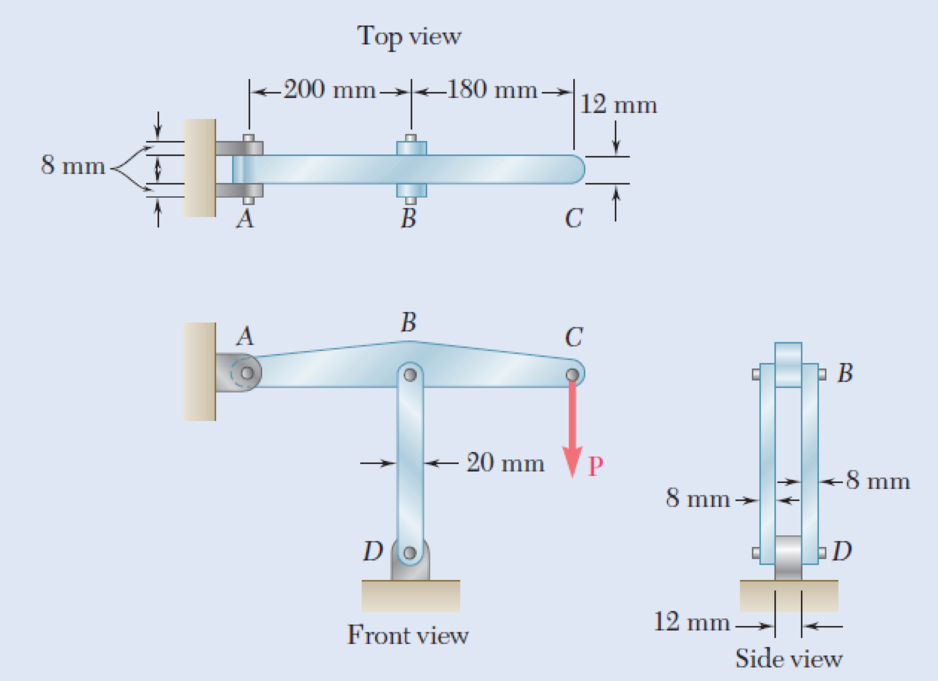
In the structure shown, an 8-mm-diameter pin is used at A, and 12-mm-diameter pins are used at B and D. Knowing that the ultimate shearing stress is 100 MPa at all connections and that the ultimate normal stress is 250 MPa in each of the two links joining B and D, determine the allowable load P if an overall factor of safety of 3.0 is desired.
Fig. P1.55
The allowable load P when an overall factor of safety of 3.0 is desired.
Answer to Problem 55P
The allowable load P when an overall factor of safety of 3.0 is desired is
Explanation of Solution
Given information:
The diameter (d) of each pin B and D is
The diameter (d) of pin A is
The ultimate shearing stress
The ultimate normal stress
Calculation:
Sketch the free body diagram of ABC as shown in Figure 1.
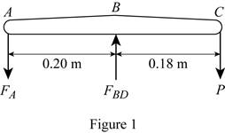
Refer to figure 1.
Take a moment about B.
Take a moment about A.
Find the area of double shear pin at A using the relation:
Substitute
Find the value of
Substitute
Find the value of P using the relation:
Substitute
Find the area of double shear pin at B and D using the relation:
Substitute
Find the force in member BD based on double shear in pins at B and D using the relation:
Substitute
Find the value of P using the relation:
Substitute
Find the area based on compression in links BD for one link as follows:
Here, d is the diameter of pin and b is the width of the section.
Substitute
Find the force in member BD of pin at B and D for one link using the relation:
Here, A is the area based on compression in link BD.
Substitute
Find the value of P using the relation:
Substitute
Based on results,
Select the smaller value of P is
Thus, the allowable load P when an overall factor of safety of 3.0 is desired is
Want to see more full solutions like this?
Chapter 1 Solutions
Mechanics of Materials, 7th Edition


- 250 mm 400 mm 1.53 Each of the two vertical links CF connecting the two horizontal members AD and EG has a 10 x 40-mm uniform rectangular cross section and is made of a steel with an ultimate strength in tension of 400 MPa, while each of the pins at C and F has a 20-mm diameter and are made of a steel with an ultimate strength in shear of 150 MPa. Determine the overall factor of safety for the links CF and the pins connecting them to the horizontal members. A 250 mm D E F 24 kNarrow_forwardIn the structure shown, an 8-mm-diameter pin is used at A, and 12-mm-diameter pins are used at B and D. Knowing that the ultimate shearing stress is 100 MPa at all connections and that the ultimate normal stress is 250 MPa in each of the two links joining B and D, determine the allowable load P if an overall factor of safety of 2.6 is desired.arrow_forwardAn annular washer distributes the load P applied to a steel rod to a timber support. The rod's diameter is 22 mm, and the washer's inner diameter is 25 mm, which is larger than the hole's permissible outer diameter. Knowing that the axial normal stress in the steel rod is 35 MPa and the average bearing stress between the washer and the timber must not exceed 5 MPa, examine the smallest allowed outer diameter, d, of the washer. %3D %3D +22 mm P Figure 4arrow_forward
- A load P is supported as shown by a steel pin that has been inserted in a short wooden member hanging from the ceiling. The ultimate strength of the wood used is 60 MPa in tension and 7.5 MPa in shear,while the ultimate strength of the steel is 145 MPa in shear. Knowing that b = 40 mm, c = 55 mm, and d = 12 mm, determine the load P if an overall factor of safety of 3.2 is desired.arrow_forwardTwo gage marks are placed exactly 250mm apart on a 12mm-diameter aluminum rod with E=73Gpa and an ultimate strength of 140Mpa. Knowing that the distance between the gage marks is 250.28mm after a load is applied, determine (a) the stress in the rod, (b) the factor of safety.arrow_forwardTwo wooden members of uniform rectangular cross section of sides a = 100 mm and b = 60 mm are joined by a simple glued joint as shown. Knowing that the ultimate stresses for the joint are σU =1.26 MPa in tension and τU = 1.50 MPa in shear and that P =6 kN, determine the factor of safety for the joint when (a) α =20°,(b) α =35°, (c) α =45°. For each of these values of α, also determine whether the joint will fail in tension or in shear if P is increased until rupture occurs.arrow_forward
- Two links BF are made of steel with a 450-MPa ultimate normal stress and has a 6x12–mm uniform rectangular cross section. Links BF are connected to members ABD and CDEF by 8-mm diameter pins; ABD and CDEF are connected together by a 10-mm diameter pin; CDEF is connected to the support by a 10-mm diameter pin; all of the pins are made of steel with a 170 MPa ultimate shearing stress. Knowing that a factor of safety of 3 is desired, determine the largest load P that may be appliedarrow_forward1.55 In the structure shown, an 8-mm-diameter pin is used at A, and 12-mm-diameter pins are used at Band D. Knowing that the ulti- mate shearing stress is 100 MPa at all connections and that the ultimate normal stress is 250 MPa in each of the two links joining B and D. determine the allowable load P if an overall factor of safety of 3.0 is desired. Top siew 12 20 12 mm Front view Side view Fig. P1.55arrow_forward1. A steel plate 5 /16 in. thick is embedded in a horizontal concrete slab and is used to anchor a high- strength vertical cable as shown. The diameter of the hole in the plate is 3 /4 in., the ultỉmate strength of the steel used is 36 ksi, and the ultimate bonding stress between plate and concrete is 300 psi. Knowing that a factor of safety of 3.60 is desired when P=2.5 kips, determine (a) the required width a of the plate, (b) the minimum depth b to which a plate of that width should be embedded in the concrete slab. (Neglect the normal stresses between the concrete and the bottom edge of the plate.arrow_forward
- A steel plate 5/16 in. thick is embedded in a horizontal concrete slab and is used to anchor a high-strength vertical cable as shown. The diameter of the hole in the plate is 3/4in., the ultimate strength of the steel used is 36 ksi, and the ultimate bonding stress between plate and concrete is 300 psi. Knowing that a factor of safety of 3.60 is desired when P = 2.5 kips, determine (a) the required width a of the plate,(b) the minimum depth b to which a plate of that width should be embedded in the concrete slab. (Neglect the normal stresses betweenthe concrete and the lower end of the plate.)arrow_forwardTwo gage marks are placed exactly 10 in. apart on a 1⁄2-in.-diameter aluminum rod with E = 10.1 x 10⁶ psi and an ultimate strength of 16 ksi. Knowing that the distance between the gage marks is 10.009 in. after a load isapplied, determine (a) the stress in the rod, (b) the factor of safety, (c) the corresponding normal stress in thewire.arrow_forwardA 9 kN tensile load will be applied to a 50 m length of steel wire with E=200 GPa. Knowing that the normal stress must not exceed 150 MPa and that the increase in the length of the wire should be at most 25 mm, determine the smallest diameter wire which can be used.arrow_forward
 Elements Of ElectromagneticsMechanical EngineeringISBN:9780190698614Author:Sadiku, Matthew N. O.Publisher:Oxford University Press
 Mechanics of Materials (10th Edition)Mechanical EngineeringISBN:9780134319650Author:Russell C. HibbelerPublisher:PEARSON
 Thermodynamics: An Engineering ApproachMechanical EngineeringISBN:9781259822674Author:Yunus A. Cengel Dr., Michael A. BolesPublisher:McGraw-Hill Education
 Control Systems EngineeringMechanical EngineeringISBN:9781118170519Author:Norman S. NisePublisher:WILEY
 Mechanics of Materials (MindTap Course List)Mechanical EngineeringISBN:9781337093347Author:Barry J. Goodno, James M. GerePublisher:Cengage Learning
 Engineering Mechanics: StaticsMechanical EngineeringISBN:9781118807330Author:James L. Meriam, L. G. Kraige, J. N. BoltonPublisher:WILEY