
Concept explainers
Videos
Consider the wye-delta system shown in Fig. 12.60. Let
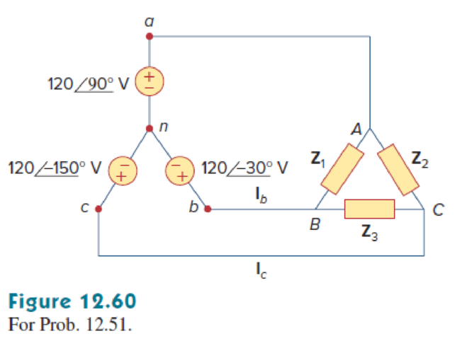
Find the phase and line currents for the
Answer to Problem 51P
The phase currents
The line currents
Explanation of Solution
Given data:
Refer to Figure 12.60 for the
In the Y-connected source:
The line to neutral voltage
The line to neutral voltage
The line to neutral voltage
In the delta-connected unbalanced load:
The impedance
The impedance
The impedance
Formula used:
Write the expression to find the line to line voltage
Here,
Write the expression to find the line to line voltage
Here,
Write the expression to find the line to line voltage
Here,
Write the expression to find the line to line current
Here,
Write the expression to find the line to line current
Here,
Write the expression to find the line to line current
Here,
Write the expression to find the line current
Here,
Write the expression to find the line current
Here,
Write the expression to find the line current
Calculation:
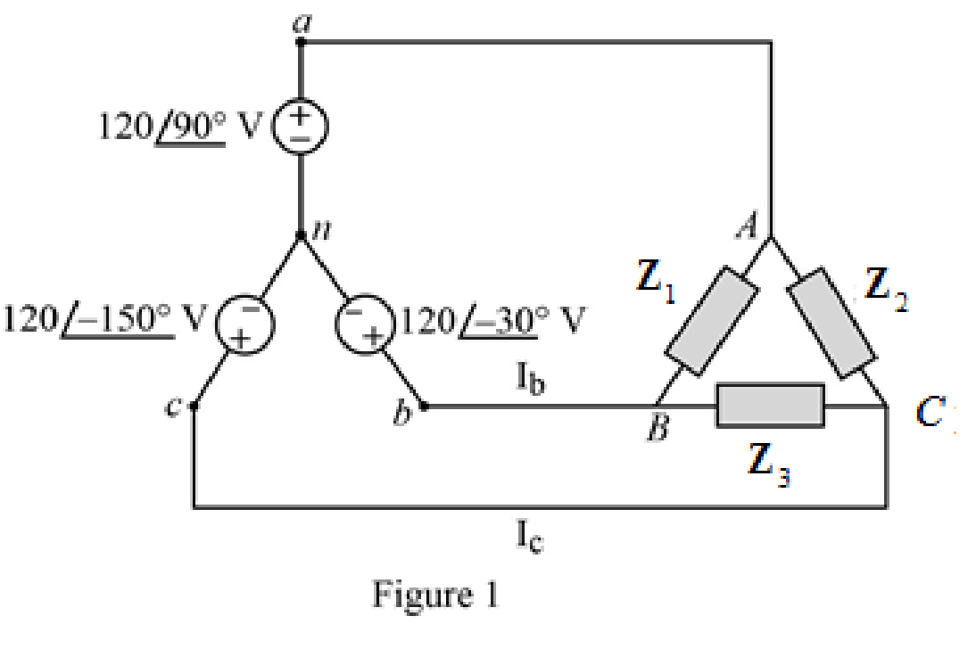
Re-draw the given Figure 12.60 as follows.
Substitute
Substitute
Substitute
Substitute
Substitute
Substitute
Or
Thus, the phase currents are,
Substitute
Substitute
Substitute
Thus, the line currents are,
PSpice simulation:
Assume the angular frequency
Write the expression to find the capacitive reactance.
Substitute
Write the expression to find the inductive reactance.
Substitute
Draw the circuit as shown in Figure 2 in PSpice, connect the
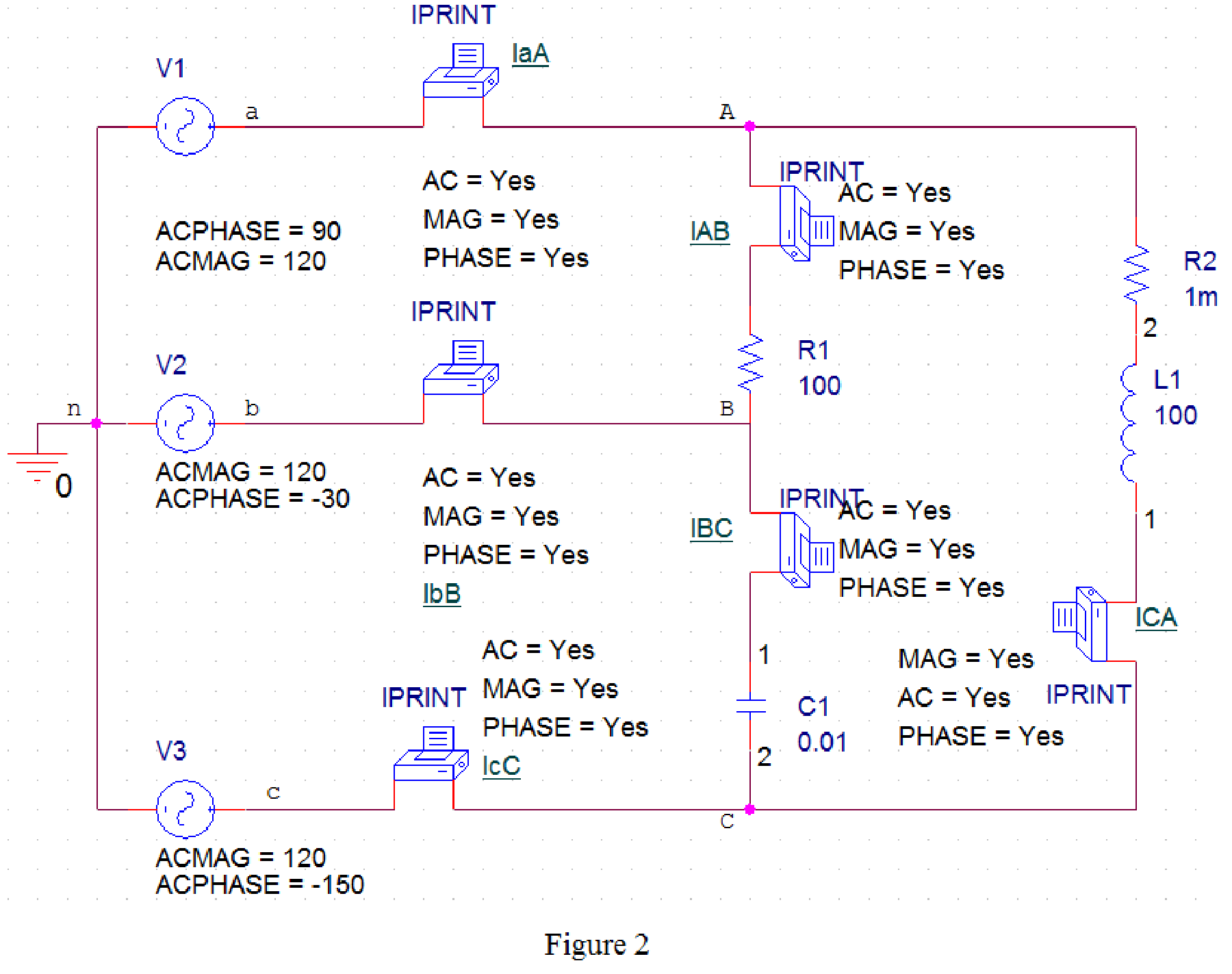
Provide the Simulation settings as in Figure 2.
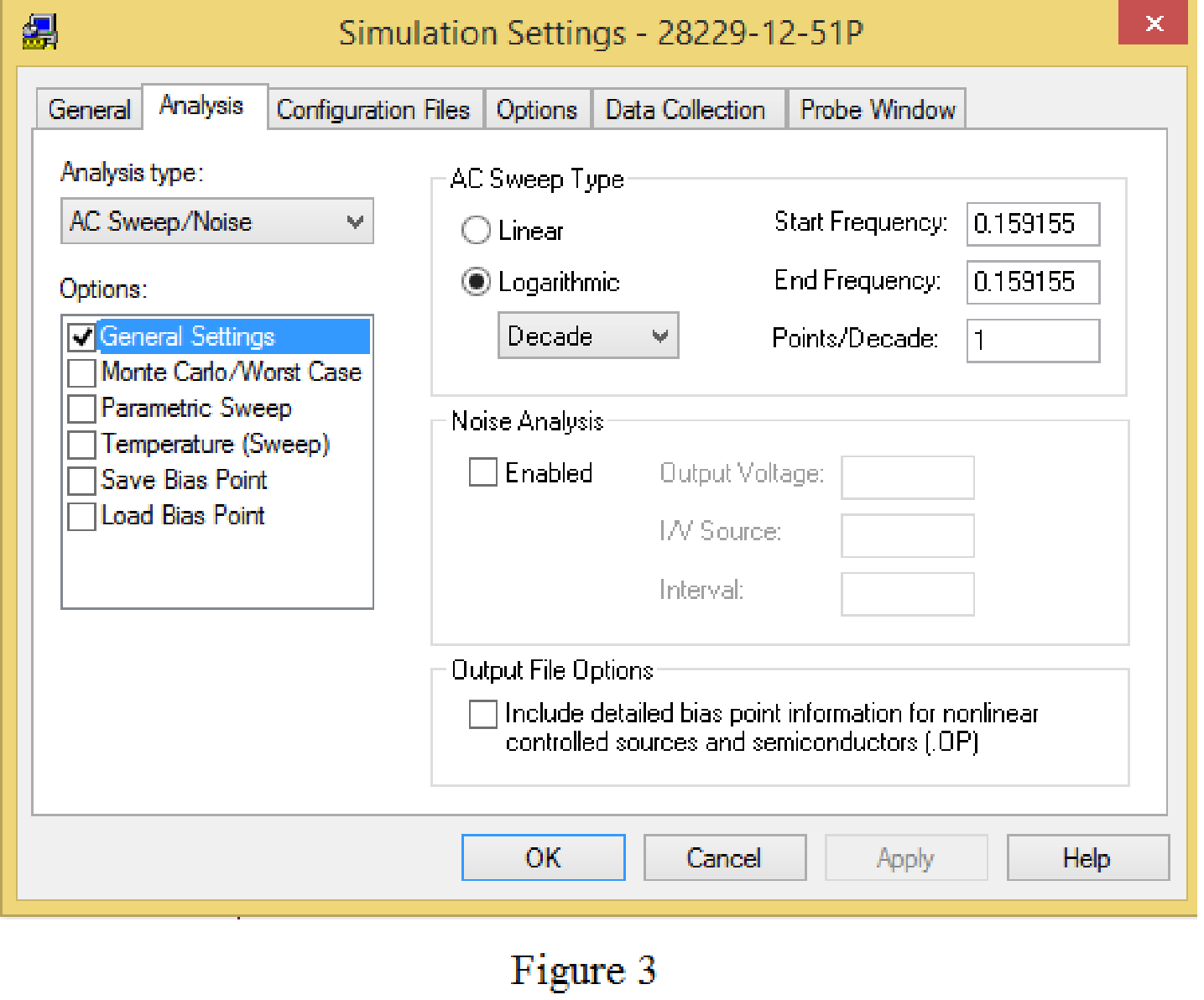
Now, run the simulation and check the output file in newly opened PSpice A/D window.
From the PSpice results the phase currents are,
FREQ IM(V_IAB) IP(V_IAB)
1.5916E-01 2.0785E+00 1.2000E+02
FREQ IM(V_IBC) IP(V_IBC)
1.5916E-01 2.0785E+00 9.0000E+01
FREQ IM(V_ICA) IP(V_ICA)
1.5916E-01 2.0785E+00 1.5000E+02
The phase current
The phase current
The phase current
From the PSpice results the line currents are,
FREQ IM(V_IaA) IP(V_IaA)
1.5916E-01 1.0759E+00 4.5000E+01
FREQ IM(V_IbB) IP(V_IbB)
1.5916E-01 1.0759E+00 1.5000E+01
FREQ IM(V_IcC) IP(V_IcC)
1.5916E-01 2.0785E+00 -1.5000E+02
The line current
The line current
The line current
Conclusion:
Thus,
The phase currents
The line currents
Want to see more full solutions like this?
Chapter 12 Solutions
Fundamentals of Electric Circuits


- Three Impedances each of (8 - j18) are connected in mesh across a three-phase 410V ac supply. Determine the phase current, line current, active power, reactive power drawn from supply. Also draw the Phasor diagram for the mesh connection and marks the Line current ,phase current line voltage and phase angle between phase current and pahse voltage. I phase current (Ip) Line current real power reactive powerarrow_forwardConsider a three-phase Y-connected source feeding a balanced- load. The phasor sum of the line currents as well as the neutral current are always zero. (a) True (b) Falsearrow_forwardIn a balanced system, the phasor sum of the line-to-line voltages and the phasor sum of the line-to-neutral voltages are always equal to zero. (a) False (b) Truearrow_forward
- Find the line currents in the unbalanced three-phase circuit of Fig. 12.26 and the real power absorbed by the load. 220-120° rms V Figure 12.26 220/0° rms V 220/120⁰ rms V b -j5Q B A www j1092 1092 Carrow_forwardA three phase, balanced delta-connected load of (4+j8) N is connected across a 400 Vrms, 3-phase balanced supply. Determine the phase current IAB- Assume the phase sequence to be ABC. Select one: O 45.72263.4° Arms O 44.72-63.4° A O 44.72-63.4° Arms O 45.722-63.4° Arms X O 44.72263.4° mArmsarrow_forwardA balanced three-phase Delta connected voltage source supplies Delta connected three-phase symmetrical load through a three-phase line at 50 Hz as shown in the figure below. Please, answer the following using ZL=0.4+j 0.8 N and Zab = Zbc = Zca=10.3+j 14.1 N. A I a Zz Z. ca I 400 20° v +1 400Z-120° v Ic SOURCE LINÉ LOAD Part F: Calculate the reactive power of the three-phase Delta load in terms of VAr. 4002-240° varrow_forward
- The impedance Z in the balanced three-phase circuit shown is 160+j120 Ω. Find 1. a) IAB, IBC, and ICA, 2. b) IaA, IbB, and IcC, 3. c) Iba, Icb, and Iac.arrow_forward11.20 For the circuit shown in Fig. P11.20, find PSPICE a) the phase currents IAB, IBC, and ICA, MULTISIM b) the line currents IaA, IbB, and Icc when Z1 = 2.4 - j0.7 N, Z2 = 8 + j6 N, and Z3 = 20 + j0 N.arrow_forward1. A balanced three-phase Y-source with Vph "E" V rms drives a Y-connected three-phase load with phase impedance ZA = " F" Q, ZB = "G" N, and Zc= "H" N. Calculate the line currents and total complex power delivered to the load. Assume that the neutrals are connected. E=230 F= 90 G= 9+j5 H= j90arrow_forward
- Given Van = 120/220° V, Z, = 2 – j2 N, and Z = 8+ j8 N for a balanced three-phase wye-wye circuit with "abc" sequence, what is the value of VCN? ZL a. TaA Von Van VAN VBN 72 VCN Ven O 135.76/120.0° V O 135.762 - 120.0° V O 164.642 - 106.0° V O 164.64/134.0° V No new data to save. Last checked at 8:00amarrow_forwardA three-phase A-connected generator has an inter- nal impedance of 0.6 + j4.8 N/4. When the load is removed from the generator, the magnitude of the terminal voltage is 34,500 V. The generator feeds a A-connected load through a transmission line with an impedance of 0.8 + j6.4 N/þ. The per-phase impedance of the load is 2877 – j864 N. a) Construct a single-phase equivalent circuit. b) Calculate the magnitude of the line current. c) Calculate the magnitude of the line voltage at the terminals of the load. d) Calculate the magnitude of the line voltage at the terminals of the source. e) Calculate the magnitude of the phase current in the load. f) Calculate the magnitude of the phase current in the source.arrow_forwardFind currents laA and lac and in the unbalanced three-phase system shown in Fig. 12.69. Let 220/0° V a 220/-120° V 220/120° V Z₁ = 2 + j, Z₂50-j30 N, Z₁ Z₁ Z₁ = 40 + j20 N, Z, = 25 Ω Z₁ A Z₁ B Z₂ To Z3arrow_forward
 Power System Analysis and Design (MindTap Course ...Electrical EngineeringISBN:9781305632134Author:J. Duncan Glover, Thomas Overbye, Mulukutla S. SarmaPublisher:Cengage Learning