
Concept explainers
Videos
Consider the single-phase three-wire system shown in Fig. 12.78. Find the current in the neutral wire and the complex power supplied by each source. Take Vs as a 220∠0°-V, 60-Hz source.
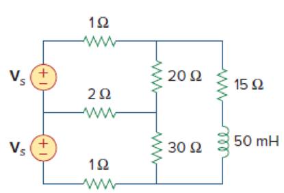
Figure 12.78
Calculate the complex power supplied by each source and the current passing through the neutral wire.
Answer to Problem 87CP
The current in the neutral wire is
Explanation of Solution
Given data:
Refer to Figure 12.78 in the textbook for a single phase three wire system.
The source voltage is
The supply frequency is
Formula used:
Write the expression to find the complex power
Here,
Write the expression to find the complex power
Here,
Write the expression to find the inductance reactance in ohms.
Here,
Write the expression to find the angular frequency.
Here,
Calculation:
Substitute
Substitute
Modify the given figure with the assumed current directions as shown in Figure.1.
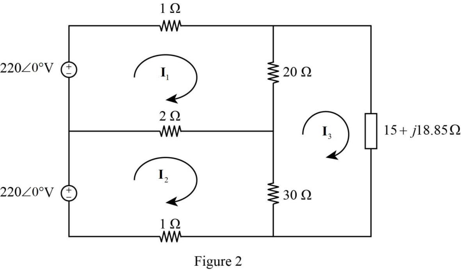
Apply Kirchhoff’s voltage law to loop 1of current
Apply Kirchhoff’s voltage law to loop 2 of current
Apply Kirchhoff’s voltage law to loop 3 of current
Represent the equation (5) (6) and (7) in matrix form.
Obtain the value of determinants as follows.
Write the expression to find the currents,
Substitute
Substitute
Substitute
Substitute
Thus, the neutral current is
Substitute
Substitute
Conclusion:
Thus, the current in the neutral wire is
Want to see more full solutions like this?
Chapter 12 Solutions
Fundamentals of Electric Circuits


- Example 12.28. A circuit when connected to 200 V, 50 Hz mains takes a current of 10 A, leading the voltage by one-twelfth of time period. Calculate (i) resistance (ii) capacitive reactance and (iii) capacitance of the circuit.arrow_forwardExample 12.23. A voltmeter, ammeter and wattmeter are suitably connected to measure the power input to an iron-cored coil. If the readings on the instruments are 110V, 2-5 A and 150 W respectively and the d.c. resistance of the copper windings of coil is 150, calculate the inductance of the coil and the power loss in the core. The supply frequency is 50 Hz.arrow_forward12.2 Find the power factor of the circuit below given that vs(t) = 120cos(377t) V. Redesign the circuit to make the power factor = 1. Vs(t) 10052 1Harrow_forward
- Problem 2 For the system shown in Figure 12.5: a) Find Is. b) Find the average power delivered to each element. c) Find the reactive power associated with each element. d) Find PT, QT, and ST. e) Find the power factor seen by the source E. R₁ ww 392 + E = 50 V/60° R3 ww 492 R₂ 12 Ω Χ 16Ω Xc 802 Figure 12.5arrow_forwardA parallel circuit of 25 – ohm resistor, 64 – mH inductor and 80 - μF capacitor connected across a 110 V, 50 Hz, single phase supply is shown in the figure below. Calculate: a.) the current in the individual element, b.) the total current drawn from the supply, c.) overall power factor of the circuit. Draw a neat phasor diagram showing IR, IL and IC.arrow_forward%3D 4=1A 430.5A Problem 12.20arrow_forward
- Asiacell|ASIACELL 3G 2G zain 1Q BartlebySolutions.. Q3: At the parallel operation of three-phase transformers: a) Give an explanation for the following cases: i. Two-lamps are glow-up i. Three-lamps are glow-up إضافة وصف. . .arrow_forwardA three-phase 240-volt table saw requires 36 kW. Calculate the load current for the table saw. The current and the voltage are out of phase by an angle of 32 degrees. Hint 1: 30kW here refers to working power, not apparent power. Hint 2: The equation for working three-phase power is found in Eq. 12.21. Hint 3: Refer to Figure 12.12 about calculating thetaarrow_forwardA 200 V single phase circuit has an apparent power of 5 KVA and reactive power of 4 KVAr. Then find (i) power factor (ii) impedance (iii) resistance (iv) reactance.arrow_forward
- 1. What is the main direct cause of reactive power in AC system? A. Resistance of transmission lines B. Inductance and capacitance in the loads C. Ideal transformer connected in the system D. Power produced by generator 2. "Reactive power in a system is dissipated generally as thermal energy?" A. TRUE B. FALSE 3. Which of the following statements are correct for three phase circuit: A. Sum of all the three phase currents is zero in unbalanced network B. Total power transfer to load is constant with time C. Neutral conductor is same size in terms of material used as in single phase conductors D. Net apparent power consumed is equal to real powerarrow_forward13. In parallel-connected ac circuit, the total current though the circuit is always equal to the phasor sum of the individual current though each element. True False 14. In a R-C parallel circuit, R=10 ohms and Xc=10 ohms, the applied voltage is leading to the circuit total current by 45 degrees (assumed applied voltage is the reference). True False 15. In a R-C series circuit, applied voltage is in phase with the total current. True Falsearrow_forwardA generator is rated 100 MW, 13.8kV and 90% power factor. The effectiveresistance is 1.5 times the ohmic resistance. The ohmic resistance isobtained by connecting two terminals to a DC source. The current andvoltage are 87.6 A and 6 V respectively. What is the DC resistance perphase? What is the effective resistance per phase? Whole Solutionarrow_forward
 Introductory Circuit Analysis (13th Edition)Electrical EngineeringISBN:9780133923605Author:Robert L. BoylestadPublisher:PEARSON
 Delmar's Standard Textbook Of ElectricityElectrical EngineeringISBN:9781337900348Author:Stephen L. HermanPublisher:Cengage Learning
 Programmable Logic ControllersElectrical EngineeringISBN:9780073373843Author:Frank D. PetruzellaPublisher:McGraw-Hill Education
 Fundamentals of Electric CircuitsElectrical EngineeringISBN:9780078028229Author:Charles K Alexander, Matthew SadikuPublisher:McGraw-Hill Education
 Electric Circuits. (11th Edition)Electrical EngineeringISBN:9780134746968Author:James W. Nilsson, Susan RiedelPublisher:PEARSON
 Engineering ElectromagneticsElectrical EngineeringISBN:9780078028151Author:Hayt, William H. (william Hart), Jr, BUCK, John A.Publisher:Mcgraw-hill Education,