
Concept explainers
Videos
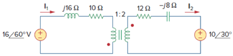
- (a) Find I1 and I2 in the circuit of Fig. 13.111 below.
- (b) Switch the dot on one of the windings. Find I1 and I2 again.
(a)
Calculate the value of currents
Answer to Problem 46P
The currents
Explanation of Solution
Given data:
Refer to Figure 13.111 in the textbook for the transformer circuit with given values.
Calculation:
In Figure 13.111, reflect the secondary circuit to the primary circuit. Consider the expression to find the input impedance
Write the Matlab code to find the input impedance.
n=2;
w=1;
R1=10;
L1=16;
ZL=12-i*8;
Z1=R1+i*(w*L1);
Zin= Z1+(ZL/n^2)
The Matlab output is given below.
Zin = 13 + 14i
From the Matlab output, the input impedance is,
Calculate the secondary side voltage source after reflection.
Substitute
The reduced circuit from Figure 13.111is drawn and it is shown in Figure 1.

From Figure 1, write the expression using Kirchhoff’s voltage law.
Substitute
Write the expression for the current
Substitute
Conclusion:
Thus, the currents
(b)
Calculate the value of currents
Answer to Problem 46P
The currents
Explanation of Solution
Calculation:
Consider that the dot in the secondary side is switched to the down side. Switching a dot will not affect the impedance
Calculate the secondary side voltage source after reflection when the dot is switched.
Substitute
The reduced circuit from Figure 13.111 is drawn and it is shown in Figure 2.
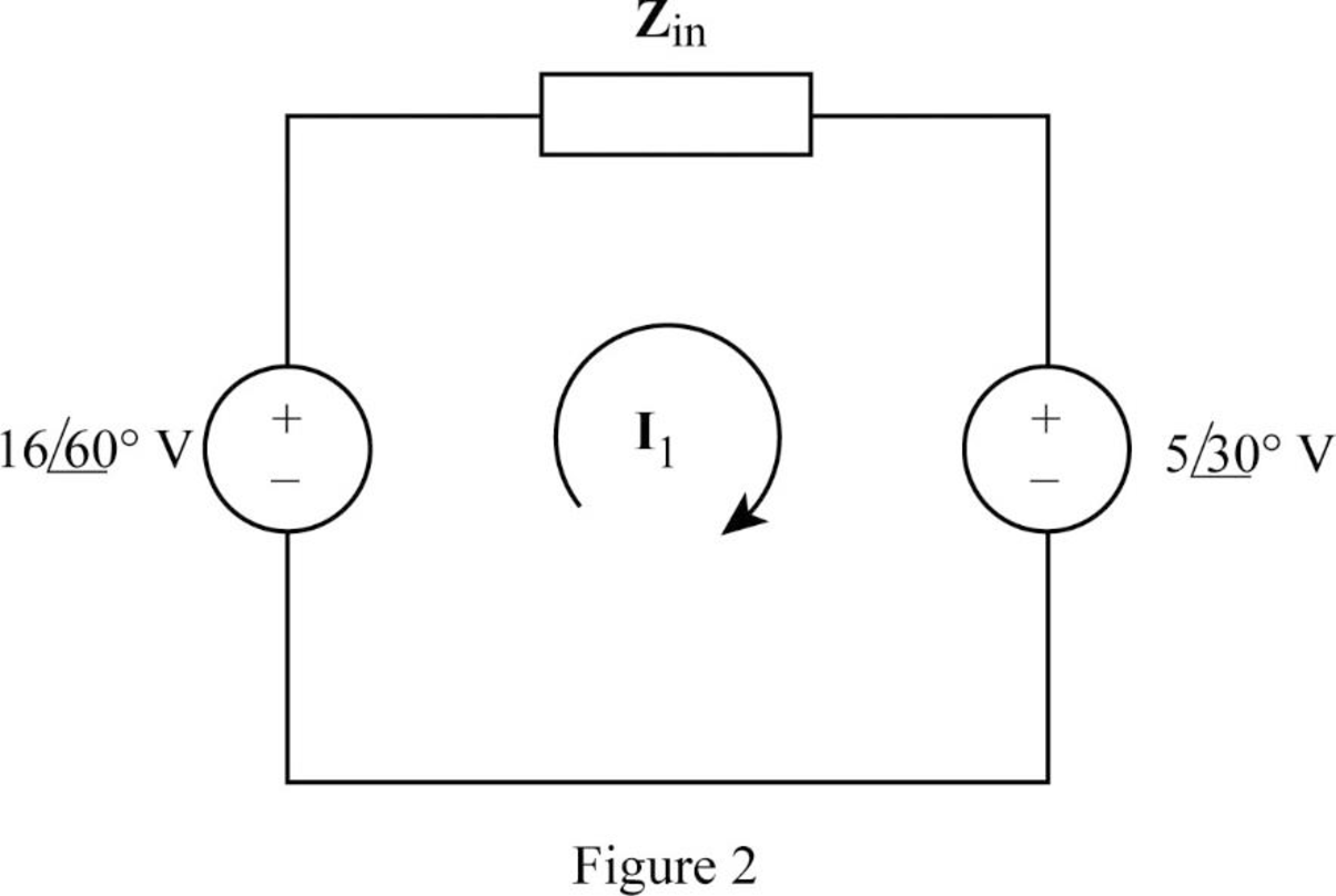
From Figure 1, write the expression using Kirchhoff’s voltage law.
Substitute
Write the expression for the current
Substitute
Conclusion:
Thus, the currents
Want to see more full solutions like this?
Chapter 13 Solutions
Fundamentals of Electric Circuits


- Construct the circuit as shown below in Multisim, R1=1kiloOhm, Voltage Source=1Vpk at 1kHz frequency, and a transformer that has a turns ratio of 1:5, Primary=1, Secondary=5. (Click the transformer to change its setting), S1 is a SPST switch D1 D2 V1 S1 1V 1kHz 0° D3 D4 2 4 C1 R1 1µF 1k2 a.) Plot the Output Waveform across R1 if S1 is closed. b.) Plot the Output Waveform across R1 if S1 is open. c.) Compute for the DC average value for the full wave bridge rectifier. d.) What kind of filter does this power supply use? duarrow_forwardProblem 3: A 60 Hz, 13.5kV/240V, single-phase ideal transformer is used to step-down the voltage of a distribution system. If the low-voltage side of the transformer is to be kept at a constant magnitude of V₂ - 240 V determine the following quantities: a) the value of the load I impedance (connected to the low-voltage side) that will cause the transformer to be fully loaded; b) the value of the load impedance found in a) referred to the high-voltage side of the transformer; c) the value of the load current referred to the low-voltage side of the transformer; and d) the value of the load current referred to the high-voltage side of the transformer.arrow_forwardQuestion Q2) Tick the correct answer for the following statements 1. An ideal transformer is connected to a 50 V battery while the load is 10062. The turn ratio is 1:2. Output power is: (d) 50 W (e) 100 W (c) 25 W (a) 0 W (b) 1 Warrow_forward
- Your aunt living in the USA sent an appliance that has impedance equal to 10 + j3 22 at 60 Hz. She instructed you to purchase a 220 V to 110 V transformer to step down the voltage since the appliance is rated 110 V. The cord that you used to connect the 220 V side of the transformer to the convenience outlet has a total impedance of 1 + j0.5 Q. You measured the voltage at the outlet and the value is 220 Vrms. The equivalent circuit is shown below: j0.5 Q 19 m IL 220 V rms 10+ j3 VL Ω 220 V : 110 V Solve for the voltage across the appliance and the current through it by either A. Referring the appliance to the transformer primary, OR B. Referring the source and cord impedance to the transformer secondary. Assign the convenience outlet voltage as the reference phasor, i.e. at 0°. Choose only one method above. After choosing, 1. Draw the circuit that would solve for V₁ and ₁. Compute all referred values and label all components. 2. Solve for V₁ and T.arrow_forwardR1=1kiloOhm, Voltage Source=1Vpk at 1kHz frequency, and a transformer that has a turns ratio of 1:5, Primary=1, Secondary=5. (Click the transformer to change its setting), S1 is a SPST switch D1 D2 3 6. V1 S1 ~) 1V 1kHz 0° 5 D3 D4 4 C1 R1 1µF 1k2 a.) Plot the Output Waveform across R1 if S1 is closed. b.) Plot the Output Waveform across R1 if S1 is open. c.) Compute for the DC average value for the full wave bridge rectifier. d.) What kind of filter does this power supply use? dumarrow_forward9- While conducting short-circuit test on a transformer the following side is short- circuited a) - H.V side , b) - Secondary side c) - L.V side d) - primary side 10- The power factor of a transformer on no load will be about a)- unity b)-o.75 c)- 0.5 d)- 0.35arrow_forward
- IV- Transformer Design You are requested to design a transformer which will have the following characteristics: Two windings, one primary and one secondary with an E-shape core. Vin = 220 V RMS 16 s Vout < 20 v RMS open circuits 14.5 V < Vout s 16 V on a 100 N resistor. 2 VA < S 35 VA apparent power. Show all steps of your design with calculation. - Indicate current in primary and secondary in both open circuit and with 100 n resistor. Simulate your transformer and show both input and output voltage with the 100 Ω load. Talk about your transformer and wire sizes.arrow_forwardYour aunt living in the USA sent an appliance that has impedance equal to 10 + j3 2 at 60 Hz. She instructed you to purchase a 220 V to 110 V transformer to step down the voltage since the appliance is rated 110 V. The cord that you used to connect the 220 V side of the transformer to the convenience outlet has a total impedance of 1 + j0.5 Q. You measured the voltage at the outlet and the value is 220 Vrms. The equivalent circuit is shown below: 1 Ω m T 220 V rms 10+ j3 V Ω 220 V : 110 V Solve for the voltage across the appliance and the current through it by either A. Referring the appliance to the transformer primary, OR B. Referring the source and cord impedance to the transformer secondary. Assign the convenience outlet voltage as the reference phasor, i.e. at 0°. Choose only one method above. After choosing, j0.5 Q +arrow_forwardYour aunt living in the USA sent an appliance that has impedance equal to 10+ j3 2 at 60 Hz. She instructed you to purchase a 220 V to 110 V transformer to step down the voltage since the appliance is rated 110 V. The cord that you used to connect the 220 V side of the transformer to the convenience outlet has a total impedance of 1 + j0.5 Q. You measured the voltage at the outlet and the value is 220 Vrms. The equivalent circuit is shown below: 1Ω mm ĪT + 10+j3 VL 220 V rms Ω 220 V : 110 V Solve for the voltage across the appliance and the current through it by either A. Referring the appliance to the transformer primary, OR B. Referring the source and cord impedance to the transformer secondary. Assign the convenience outlet voltage as the reference phasor, i.e. at 0°. Choose only one method above. After choosing, 1. Draw the circuit that would solve for V₁ and T. Compute all referred values and label all components. 2. Solve for V and I. j0.5 Q +arrow_forward
- Your aunt living in the USA sent an appliance that has impedance equal to 10 + j3 2 at 60 Hz. She instructed you to purchase a 220 V to 110 V transformer to step down the voltage since the appliance is rated 110 V. The cord that you used to connect the 220 V side of the transformer to the convenience outlet has a total impedance of 1 + j0.5 Q. You measured the voltage at the outlet and the value is 220 Vrms. The equivalent circuit is shown below: j0.5 Ω 1Ω mm N220 V rms 10 + j3 V₁ Ω 220 V 110 V Solve for the voltage across the appliance and the current through it by either A. Referring the appliance to the transformer primary, OR B. Referring the source and cord impedance to the transformer secondary. Assign the convenience outlet voltage as the reference phasor, i.e. at 0°. Choose only one method above. After choosing, 1. Draw the circuit that would solve for V₁ and I. Compute all referred values and label all components. 2. Solve for V₁ and I₁. S + Iarrow_forwardYour aunt living in the USA sent an appliance that has impedance equal to 10 + j3 2 at 60 Hz. She instructed you to purchase a 220 V to 110 V transformer to step down the voltage since the appliance is rated 110 V. The cord that you used to connect the 220 V side of the transformer to the convenience outlet has a total impedance of 1 + j0.5 Q. You measured the voltage at the outlet and the value is 220 Vrms. The equivalent circuit is shown below: j0.5 Q 19 ww + (N) 220 V rms 10+ j3 VL Ω 220 V : 110 V Solve for the voltage across the appliance and the current through it by either A. Referring the appliance to the transformer primary, OR B. Referring the source and cord impedance to the transformer secondary. Assign the convenience outlet voltage as the reference phasor, i.e. at 0°. Choose only one method above. After choosing, 1. Draw the circuit that would solve for V₁ and T. Compute all referred values and label all components. 2. Solve for V and I.arrow_forwardYour aunt living in the USA sent an appliance that has impedance equal to 10+ j3 2 at 60 Hz. She instructed you to purchase a 220 V to 110 V transformer to step down the voltage since the appliance is rated 110 V. The cord that you used to connect the 220 V side of the transformer to the convenience outlet has a total impedance of 1 + j0.5 Q. You measured the voltage at the outlet and the value is 220 Vrms. The equivalent circuit is shown below: 1Ω m IL + (N) 220 V rms 10+ j3 VL 22 220 V 110 V Solve for the voltage across the appliance and the current through it by either A. Referring the appliance to the transformer primary, OR B. Referring the source and cord impedance to the transformer secondary. Assign the convenience outlet voltage as the reference phasor, i.e. at 0°. Choose only one method above. After choosing, 1. Draw the circuit that would solve for V₁ and T₁. Compute all referred values and label all components. j0.5 Ωarrow_forward
 Introductory Circuit Analysis (13th Edition)Electrical EngineeringISBN:9780133923605Author:Robert L. BoylestadPublisher:PEARSON
 Delmar's Standard Textbook Of ElectricityElectrical EngineeringISBN:9781337900348Author:Stephen L. HermanPublisher:Cengage Learning
 Programmable Logic ControllersElectrical EngineeringISBN:9780073373843Author:Frank D. PetruzellaPublisher:McGraw-Hill Education
 Fundamentals of Electric CircuitsElectrical EngineeringISBN:9780078028229Author:Charles K Alexander, Matthew SadikuPublisher:McGraw-Hill Education
 Electric Circuits. (11th Edition)Electrical EngineeringISBN:9780134746968Author:James W. Nilsson, Susan RiedelPublisher:PEARSON
 Engineering ElectromagneticsElectrical EngineeringISBN:9780078028151Author:Hayt, William H. (william Hart), Jr, BUCK, John A.Publisher:Mcgraw-hill Education,