
Concept explainers
Videos
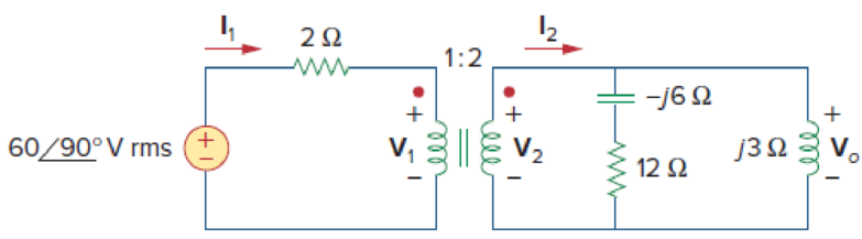
For the ideal transformer circuit of Fig. 13.122 below, find:
- (a) I1 and I2,
- (b) V1, V2, and Vo,
- (c) the complex power supplied by the source.
(a)
Calculate the currents
Answer to Problem 57P
The value of currents
Explanation of Solution
Given data:
Refer to Figure 13.122 in the textbook for the transformer circuit.
The value of n from the given figure is 2.
Calculation:
From Figure 13.122, calculate the load impedance
In Figure 13.122, reflect the load of
Substitute 2 for
Consider the expression for the impedance
Substitute
From Figure 1, write the expression for the current
Substitute
Write the expression for the current
Substitute
Conclusion:
Thus, the value of currents
(b)
Calculate the voltages
Answer to Problem 57P
The value of voltages
Explanation of Solution
Calculation:
Apply Kirchhoff's voltage law to the primary loop contains current
Substitute
Write the expression for the voltage
Substitute 2 for n and
Write the expression for the output voltage
Substitute
Conclusion:
Thus, The value of voltages
(c)
Calculate the complex power supplied by the source.
Answer to Problem 57P
The complex power supplied by the source is
Explanation of Solution
Calculation:
The conjugate of the current
Write the expression for the complex power supplied by the source.
Write the Matlab code to find the required complex power.
V=i*60;
I1_C=8.8753-i*24.3318;
S=V*I1_C
The output of the Matlab code is given as follows.
S = 1459.91 + 532.52i
From the Matlab output, the complex power is,
Conclusion:
Thus, the complex power supplied by the source is
Want to see more full solutions like this?
Chapter 13 Solutions
Fundamentals of Electric Circuits


- As given in the figure, an ideal transformer with a 2: 1 winding ratio is fed from a 240 Volt source with an internal impedance of 8 + j6 Ω and transfers maximum power to the load impedance connected at its secondary. So, which of the following is the V2 voltage in the secondary?arrow_forward13. A transformer has a turns ratio of 5. If a 100-S resistor is connected across the secondary, what is its resistance referred to the primary? A. 500 2 C. 1000 N D.2500 2 B. 20 2arrow_forwardIn the ideal transformer circuit of Fig. 13.38, find and the complexpower supplied by the source.arrow_forward
- Your aunt living in the USA sent an appliance that has impedance equal to 10 + j3 2 at 60 Hz. She instructed you to purchase a 220 V to 110 V transformer to step down the voltage since the appliance is rated 110 V. The cord that you used to connect the 220 V side of the transformer to the convenience outlet has a total impedance of 1 + j0.5 Q. You measured the voltage at the outlet and the value is 220 Vrms. The equivalent circuit is shown below: j0.5 Ω 1Ω mm N220 V rms 10 + j3 V₁ Ω 220 V 110 V Solve for the voltage across the appliance and the current through it by either A. Referring the appliance to the transformer primary, OR B. Referring the source and cord impedance to the transformer secondary. Assign the convenience outlet voltage as the reference phasor, i.e. at 0°. Choose only one method above. After choosing, 1. Draw the circuit that would solve for V₁ and I. Compute all referred values and label all components. 2. Solve for V₁ and I₁. S + Iarrow_forwardA 2000 VA transformer has a primary winding resistance of 0.3 Ω and a secondary winding resistanceof 0.0012 Ω. The primary and secondary voltages are 200 V and 100 V respectively. Find the full load copper loss.arrow_forwardYour aunt living in the USA sent an appliance that has impedance equal to 10 + j3 2 at 60 Hz. She instructed you to purchase a 220 V to 110 V transformer to step down the voltage since the appliance is rated 110 V. The cord that you used to connect the 220 V side of the transformer to the convenience outlet has a total impedance of 1 + j0.5 Q. You measured the voltage at the outlet and the value is 220 Vrms. The equivalent circuit is shown below: 1 Ω m T 220 V rms 10+ j3 V Ω 220 V : 110 V Solve for the voltage across the appliance and the current through it by either A. Referring the appliance to the transformer primary, OR B. Referring the source and cord impedance to the transformer secondary. Assign the convenience outlet voltage as the reference phasor, i.e. at 0°. Choose only one method above. After choosing, j0.5 Q +arrow_forward
- Your aunt living in the USA sent an appliance that has impedance equal to 10+ j3 2 at 60 Hz. She instructed you to purchase a 220 V to 110 V transformer to step down the voltage since the appliance is rated 110 V. The cord that you used to connect the 220 V side of the transformer to the convenience outlet has a total impedance of 1 + j0.5 Q. You measured the voltage at the outlet and the value is 220 Vrms. The equivalent circuit is shown below: 1Ω mm ĪT + 10+j3 VL 220 V rms Ω 220 V : 110 V Solve for the voltage across the appliance and the current through it by either A. Referring the appliance to the transformer primary, OR B. Referring the source and cord impedance to the transformer secondary. Assign the convenience outlet voltage as the reference phasor, i.e. at 0°. Choose only one method above. After choosing, 1. Draw the circuit that would solve for V₁ and T. Compute all referred values and label all components. 2. Solve for V and I. j0.5 Q +arrow_forwardYour aunt living in the USA sent an appliance that has impedance equal to 10 + j3 2 at 60 Hz. She instructed you to purchase a 220 V to 110 V transformer to step down the voltage since the appliance is rated 110 V. The cord that you used to connect the 220 V side of the transformer to the convenience outlet has a total impedance of 1 + j0.5 Q. You measured the voltage at the outlet and the value is 220 Vrms. The equivalent circuit is shown below: j0.5 Q 19 ww + (N) 220 V rms 10+ j3 VL Ω 220 V : 110 V Solve for the voltage across the appliance and the current through it by either A. Referring the appliance to the transformer primary, OR B. Referring the source and cord impedance to the transformer secondary. Assign the convenience outlet voltage as the reference phasor, i.e. at 0°. Choose only one method above. After choosing, 1. Draw the circuit that would solve for V₁ and T. Compute all referred values and label all components. 2. Solve for V and I.arrow_forwardYour aunt living in the USA sent an appliance that has impedance equal to 10+ j3 2 at 60 Hz. She instructed you to purchase a 220 V to 110 V transformer to step down the voltage since the appliance is rated 110 V. The cord that you used to connect the 220 V side of the transformer to the convenience outlet has a total impedance of 1 + j0.5 Q. You measured the voltage at the outlet and the value is 220 Vrms. The equivalent circuit is shown below: 1Ω m IL + (N) 220 V rms 10+ j3 VL 22 220 V 110 V Solve for the voltage across the appliance and the current through it by either A. Referring the appliance to the transformer primary, OR B. Referring the source and cord impedance to the transformer secondary. Assign the convenience outlet voltage as the reference phasor, i.e. at 0°. Choose only one method above. After choosing, 1. Draw the circuit that would solve for V₁ and T₁. Compute all referred values and label all components. j0.5 Ωarrow_forward
- For the linear transformer in Fig. 13.26(a), find the equivalentnetwork.arrow_forwardIn the circuit shown in the figure below, if the primary coil has the number of turns of 18, then the number of turns in the secondary coil required, such that maximum power will be delivered to the load of 50 is. 45 0 ww Ideal Transformer ww 00000,arrow_forwardYour aunt living in the USA sent an appliance that has impedance equal to 10 + j3 22 at 60 Hz. She instructed you to purchase a 220 V to 110 V transformer to step down the voltage since the appliance is rated 110 V. The cord that you used to connect the 220 V side of the transformer to the convenience outlet has a total impedance of 1 + j0.5 Q. You measured the voltage at the outlet and the value is 220 Vrms. The equivalent circuit is shown below: j0.5 Q 19 m IL 220 V rms 10+ j3 VL Ω 220 V : 110 V Solve for the voltage across the appliance and the current through it by either A. Referring the appliance to the transformer primary, OR B. Referring the source and cord impedance to the transformer secondary. Assign the convenience outlet voltage as the reference phasor, i.e. at 0°. Choose only one method above. After choosing, 1. Draw the circuit that would solve for V₁ and ₁. Compute all referred values and label all components. 2. Solve for V₁ and T.arrow_forward
 Introductory Circuit Analysis (13th Edition)Electrical EngineeringISBN:9780133923605Author:Robert L. BoylestadPublisher:PEARSON
 Delmar's Standard Textbook Of ElectricityElectrical EngineeringISBN:9781337900348Author:Stephen L. HermanPublisher:Cengage Learning
 Programmable Logic ControllersElectrical EngineeringISBN:9780073373843Author:Frank D. PetruzellaPublisher:McGraw-Hill Education
 Fundamentals of Electric CircuitsElectrical EngineeringISBN:9780078028229Author:Charles K Alexander, Matthew SadikuPublisher:McGraw-Hill Education
 Electric Circuits. (11th Edition)Electrical EngineeringISBN:9780134746968Author:James W. Nilsson, Susan RiedelPublisher:PEARSON
 Engineering ElectromagneticsElectrical EngineeringISBN:9780078028151Author:Hayt, William H. (william Hart), Jr, BUCK, John A.Publisher:Mcgraw-hill Education,