
Videos
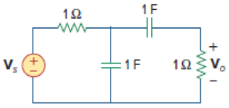
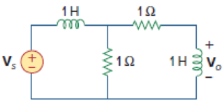
Determine the center frequency and bandwidth of the band-pass filters in Fig. 14.88.
(a)
Find the center frequency and bandwidth of the band-pass filter shown in Figure 14.88(a).
Answer to Problem 57P
The value of the center frequency
Explanation of Solution
Given data:
Refer to Figure 14.88(a) in the textbook.
Formula used:
Write the expression to calculate the impedance of the passive elements resistor, inductor and capacitor in s-domain.
Here,
Calculation:
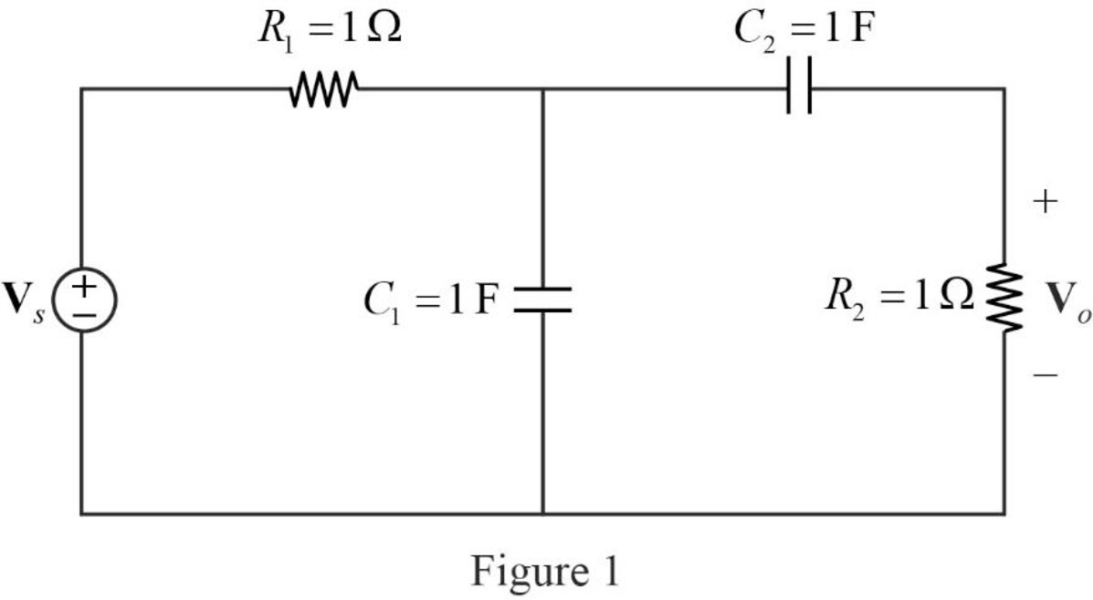
The given circuit is drawn as Figure 1.
Use equation (1) to find
Use equation (1) to find
Use equation (3) to find
Use equation (3) to find
The s-domain circuit of the Figure 1 is drawn as Figure 2.
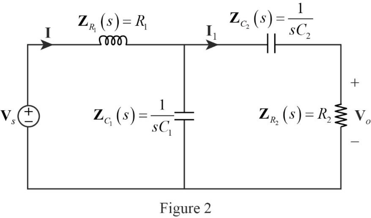
Write the general expression to calculate the transfer function of the circuit in Figure 2.
Here,
Refer to Figure 2, the series connected impedances
Therefore, the equivalent impedance is calculated as follows.
Substitute
Refer to the given data. The value of the resistors
Substitute
Simplify the above equation to find
The reduced circuit of Figure 2 is drawn as Figure 3.
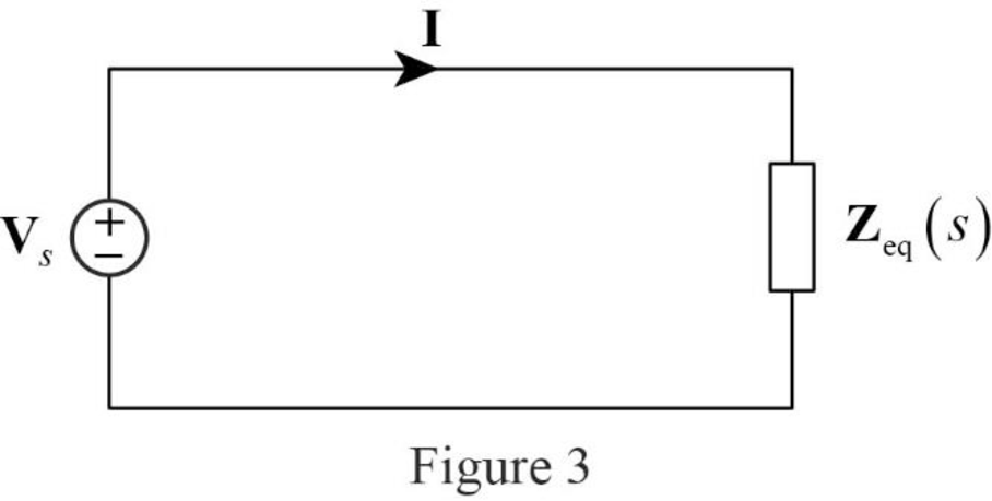
Refer to the Figure 3, the current through the circuit is expressed as,
Apply current division rule on Figure 2 to find
Substitute
Substitute
Refer to Figure 2, the output voltage
Substitute
Rearrange the above equation to find
Substitute
Compare the denominator factor of above equation with the standard quadratic equation
Substitute
Take square root on both sides of the above equation to find
Write the expression to calculate the bandwidth of the band-pass filter.
Substitute
Conclusion:
Thus, the value of the center frequency
(b)
Find the center frequency and bandwidth of the band-pass filter shown in Figure 14.88(b).
Answer to Problem 57P
The value of the center frequency
Explanation of Solution
Given data:
Refer to Figure 14.88(b) in the textbook.
Calculation:
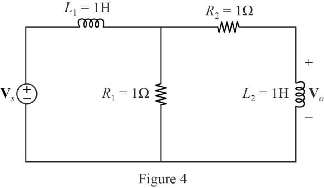
The given circuit is drawn as Figure 4.
Use equation (1) to find
Use equation (1) to find
Use equation (2) to find
Use equation (2) to find
The s-domain circuit of the Figure 4 is drawn as Figure 5.
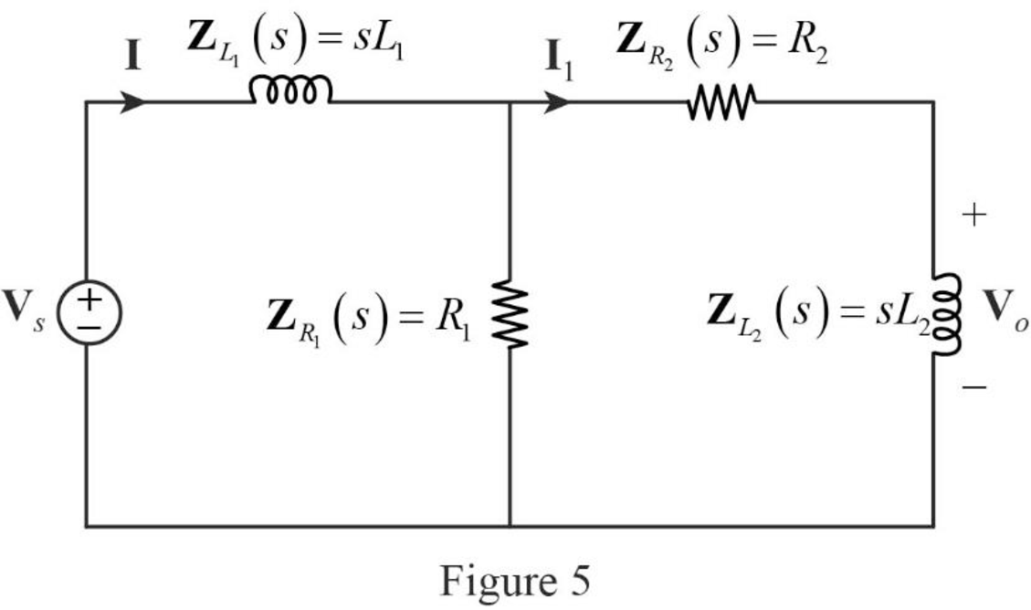
Write the general expression to calculate the transfer function of the circuit in Figure 5.
Refer to Figure 5, the series connected impedances
Therefore, the equivalent impedance is calculated as follows.
Substitute
Refer to the given data. The value of the resistors
Substitute
Simplify the above equation to find
The reduced circuit of Figure 5 is drawn as Figure 6.

Refer to the Figure 6, the current through the circuit is expressed as,
Apply current division rule on Figure 5 to find
Substitute
Substitute
Refer to Figure 5, the output voltage
Substitute
Rearrange the above equation to find
Substitute
Compare the denominator factor of above equation with the standard quadratic equation
Substitute
Take square root on both sides of the above equation to find
Substitute
Conclusion:
Thus, the value of the center frequency
Want to see more full solutions like this?
Chapter 14 Solutions
Fundamentals of Electric Circuits


- 14. The Bandwidth a) 0.5 Hz b) 500 K Hz for Ku Band is: c) 0.5 M Hz d) 500M Hz.arrow_forward1. The mathematical expression of the frequency spectrum of a general FM signal shows that it has technically a limited bandwidth a wide bandwidth an infinite bandwidth narrow bandwidth none of the choices 2. The break frequency for commercial FM broadcast of the preemphasis and deemphasis network is 2.122 kHz 2122 kHz 75 kHz 75 Hz none of the choicesarrow_forwardExample 21: A series R-L-C circuit has R = 102, L = 0.1 H and C = 8 μF. Determine, (i) Resonant frequency (ii) Q-factor of circuit at resonance (iii) The half power frequenciesarrow_forward
- Answer the following with illustration and solution. 1.) Calculate the frequency of this low-pass filter given a resistor value of 1.2k ohms and a capacitor value of 4.7 microfarad. This is ithe example that might help.arrow_forwardCalculate Resonance Frequency, Cutoff Frequencies, Bandwidth, and Quality Factor for the RLC Circuit. R3 470 R4 L3 C3 V1 2700 470uH 10NFarrow_forward& 121L Midterm Theory 98. Which of these formulas would be used to determine the resonant value of inductance? a. b. C. fR C= = 1 2TVLC 1 4T²f²C 1 4π²f²Larrow_forward
- 1. A parallel R-L-C circuit is fed by a constant current source of variable frequency. The circuit resonates at 100 kHz and the Q-factor measured at this frequency is 5. Find the frequencies at which the amplitude of the voltage across the circuit falls to (a) 70.7% (b) 50% of the resonant frequency amplitude. [(a) 90.5 kHz ; 110.5 kHz (b) 84.18 kHz ; 118.8 kHz]arrow_forwardFind the bandwidth of a series resonant circuit having a resonant frequency of 6000 Hz and a Q, of 15.arrow_forwardFor the circuits in Fig. 14.81, find the resonant frequency , the quality factor Q, and the bandwidth B. 202 www 622 www (a) ΤΗ 0.4 F Figure 14.81 For Prob. 14.42. m 20 mH 2kQ2 (b) 3 µF :6 μFarrow_forward
- Fig. 9 shows the Butterworth lowpass filter. i. ii. Determine the order of the filter. Given that the cut-off frequency is 15HZ, determine the value of L, C1 and C2. m L 10 C: io(1)arrow_forwarda)find magnitude of G(iw)b) find angle phase of G(iw)c)plot asymtotic bode diagramarrow_forwardDiscussions: 1) For the following filter, 0.15pF Vout Vin 3300 2) Explain what a band-pass filter is, and how it differs from either a low-pass or a high-pass filter circuit. Also, explain what a band-stop filter is, and draw Bode plots representative of both band-pass and band-stop filter types.arrow_forward
 Introductory Circuit Analysis (13th Edition)Electrical EngineeringISBN:9780133923605Author:Robert L. BoylestadPublisher:PEARSON
 Delmar's Standard Textbook Of ElectricityElectrical EngineeringISBN:9781337900348Author:Stephen L. HermanPublisher:Cengage Learning
 Programmable Logic ControllersElectrical EngineeringISBN:9780073373843Author:Frank D. PetruzellaPublisher:McGraw-Hill Education
 Fundamentals of Electric CircuitsElectrical EngineeringISBN:9780078028229Author:Charles K Alexander, Matthew SadikuPublisher:McGraw-Hill Education
 Electric Circuits. (11th Edition)Electrical EngineeringISBN:9780134746968Author:James W. Nilsson, Susan RiedelPublisher:PEARSON
 Engineering ElectromagneticsElectrical EngineeringISBN:9780078028151Author:Hayt, William H. (william Hart), Jr, BUCK, John A.Publisher:Mcgraw-hill Education,