
Concept explainers
Videos
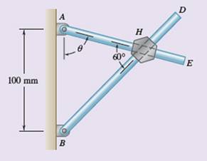
Two rods AE and BD pass through holes drilled into a hexagonal block. (The holes are drilled in different planes so that the rods will not touch each other.) Knowing that rod AE has an angular velocity of 20 rad/s clockwise and an angular acceleration of 4 rad/s2 counterclockwise when
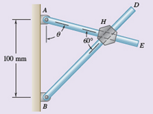
Fig. P15.257
(a)
Relative velocity of block with respect to each rod.
Answer to Problem 15.257RP
Relative velocity of block with respect to each rod
Explanation of Solution
Given information:
The angular velocity and angular acceleration of rod AE is
The Coriolis acceleration is a combination of
The Coriolis acceleration id defined as
The velocity is defined as
The normal acceleration is defined as
The tangential acceleration is defined as
Calculation:
When
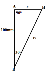
Apply sine rule,
Therefore,
The angle
Assume, the relative velocity of slider H on rod AH is
The velocity of point
The acceleration of point
The relevant Coriolis acceleration is
The velocity of point H,
The acceleration of point H
Assume, the relative velocity of slider H on rod BD is
The velocity of point
The acceleration of point
The relevant Coriolis acceleration
The velocity of point H,
The acceleration of point H
Equate
Therefore, the relative velocities
Conclusion:
The relative velocities of each rod
(b)
Relative acceleration of block with respect to each rod.
Answer to Problem 15.257RP
Relative acceleration of block with respect to each rod
Explanation of Solution
Given information:
The angular velocity and angular acceleration of rod AE is
The Coriolis acceleration is a combination of
The Coriolis acceleration id defined as
The velocity is defined as
The normal acceleration is defined as
The tangential acceleration is defined as
Calculation:
According to sub part a
Substitute for
Therefore
Therefore
Conclusion:
The relative acceleration of each rod
Want to see more full solutions like this?
Chapter 15 Solutions
Vector Mechanics For Engineers


- Both 15-cm-radius wheels roll without slipping on the horizontal surface. Knowing that the distance AD is 12.5 cm, the distance BE is 10 cm, that D has a velocity of 30 cm/s to the right and acceleration of E is 60 cm/s? to the left, determine the angular velocity and angular acceleration of link AB, angular velocity and angular acceleration of both wheels. Also determine the acceleration of point C. | 30 y Wheel 1 45 cm Wheel 2 /A 15cm 10 cm VD=30 cm/s B aE=60 cm/s2 15 cm 12.5 cmarrow_forwardRequired information NOTE: This is a multi-part question. Once an answer is submitted, you will be unable to return to this part. For a 5-m steel beam AE, the acceleration of point A is 2.5 m/s² downward and the angular acceleration of the beam is 1.5 rad/s2 counterclockwise. Knowing that at the instant considered the angular velocity of the beam is zero, determine the acceleration of cable B and cable D. A -1.5 m- B Determine the acceleration of cable B The acceleration of cable Bis 2 m 1.375 5 m/s2. D -1.5 m- Earrow_forwardProblem (5) The rectangular block shown rotates about the diagonal OA with a constant angular velocity of 6.76 rad/s. Knowing that the rotation is counterclockwise as viewed from A, determine the velocity and acceleration of point B at the instant shown. 240 mm 100 mm 312 mm B 312 mmarrow_forward
- 5.- Knowing that at the instant shown bar AB has an angular velocity of 4 rad/s and an angular acceleration of 2 rad/s?, both clockwise, determine the angular acceleration (a) of bar BD, (b) of bar DE by using the vector approach. 100 mm 175 mm - B A 200 mm 75 mm D Earrow_forwardThe 200-mm-radius disk rolls without sliding on the surface shown. Knowing that the distance BG is 160 mm and that at the instant shown the disk has an angular velocity of 5.50 rad/s counterclockwise and an angular acceleration of 7.00 rad/s² clockwise, determine the acceleration of A. A 730 mm 200 mm Barrow_forwardProblem (8) The belt shown moves over two pulleys without slipping. At the instant shown the pulleys are rotating clockwise and the speed of point B on the belt is 4 m/s, increasing at the rate of 32 m/s?. Determine, at this instant, (a) the angular velocity and angular acceleration of each pulley, (b) the acceleration of point P on pulley C. B 160 mm fi00 mmarrow_forward
- If crank AB rotates with an angular velocity of wAB angular acceleration a AB = 6 rad/s? at the instant shown, determine: 1.1. The angular velocity of rod BC and the velocity of the slider block 1.2. The angular acceleration of rod BC and the linear acceleration of = 5 rad/s and an 0.5 m 0,3 m B 60° 30° WAB slider Block. 1.3. Locate the instantaneous center (IC) of the rod BC. CABarrow_forwardA series of small machine components being moved by a conveyor belt pass over a 120 mm radius idler pulley. At the instant shown, the velocity of Point A is 300 mm/s to the left and its acceleration is 180 mm/s2 to the right. Determine (a) the angular velocity and angular acceleration of the idler pulley, (b) the total acceleration of the machine component at B.arrow_forward0.2 m 0.25 m D E 0.6 m- Knowing that at the instant shown the angular velocity of rod AB is 15 rad/s clockwise, determine (a) the angular velocity of rod BD. (b) the velocity of the midpoint of rod BD. In the position shown, bar AB has an angular velocity of 4 rad/s clockwise. Determine the angular velocity of bars BD and DE. 200 mm 75 mm D 175 mm - 100 mm Earrow_forward
- A Rod slides along the ground and the wall as shown. If the velocity of end B is 2 m/s downwards, Determine (a) the angular velocity of AB, (b) the velocity of end A. 500 mm 125 mm B 300 mmarrow_forwardA The 18-in.-radius fly wheel is rigidly attached to a 1.5-in. -radius shaft that can roll along parallel rails. Knowing that at the instant shown the center of the shaft has a velocity of 1.2 in/s and an acceleration of 0.5 in/s?, both directed down to the left, determine the acceleration (a) of point A, (b) of point B. 18 in. 20 Вarrow_forward6) Bar BDE is attached to two links AB and CD. Knowing that at the instant shown link AB rotates with a constant angular velocity of 3 rad/s clockwise, determine the acceleration (a) of point D, (b) of point E. 19.1 cm 19.1 cm C -30.5 cm -22.9 cm- B ODarrow_forward
 Elements Of ElectromagneticsMechanical EngineeringISBN:9780190698614Author:Sadiku, Matthew N. O.Publisher:Oxford University Press
 Mechanics of Materials (10th Edition)Mechanical EngineeringISBN:9780134319650Author:Russell C. HibbelerPublisher:PEARSON
 Thermodynamics: An Engineering ApproachMechanical EngineeringISBN:9781259822674Author:Yunus A. Cengel Dr., Michael A. BolesPublisher:McGraw-Hill Education
 Control Systems EngineeringMechanical EngineeringISBN:9781118170519Author:Norman S. NisePublisher:WILEY
 Mechanics of Materials (MindTap Course List)Mechanical EngineeringISBN:9781337093347Author:Barry J. Goodno, James M. GerePublisher:Cengage Learning
 Engineering Mechanics: StaticsMechanical EngineeringISBN:9781118807330Author:James L. Meriam, L. G. Kraige, J. N. BoltonPublisher:WILEY