
Concept explainers
Videos
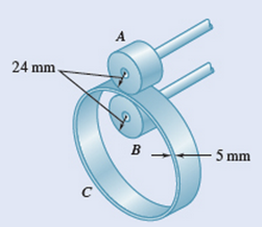
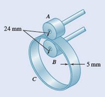
Ring C has an inside radius of 55 mm and an outside radius of 60 mm and is positioned between two wheels A and B, each of 24-mm outside radius. Knowing that wheel A rotates with a constant angular velocity of 300 rpm and that no slipping occurs, determine (a) the angular velocity of ring C and of wheel B, (b) the acceleration of the points on A and B that are in contact with C.
Fig. . P15.26
(a)
The angular velocity of ring
Answer to Problem 15.26P
The angular velocity of ring
The angular velocity of wheel
Explanation of Solution
Given information:
Inside radius of ring
Outside radius of ring
Outside radius of wheels
Wheel
No slipping occurs.
Concept used:
The velocity
Calculation:
The velocity of the point
The point of ring
Here, the outer radius of the ring
The ponit of wheel
Here, the inner radius of the ring
The angular velocity of ring
The angular velocity of wheel
Conclusion:
The angular velocity of ring
The angular velocity of wheel
(b)
The accelerations of the points on
Answer to Problem 15.26P
The accelerations of the point on
The accelerations of the point on
Explanation of Solution
Given information:
Inside radius of ring
Outside radius of ring
Outside radius of wheels
Wheel
No slipping occurs.

Concept used:
The acceleration
Calculation:
The acceleration of the point
Consider the point on
Consider the point on
The accelerations of the point on
The accelerations of the point on
Conclusion:
The accelerations of the point on
The accelerations of the point on
Want to see more full solutions like this?
Chapter 15 Solutions
Vector Mechanics For Engineers


- A The 18-in.-radius fly wheel is rigidly attached to a 1.5-in. -radius shaft that can roll along parallel rails. Knowing that at the instant shown the center of the shaft has a velocity of 1.2 in/s and an acceleration of 0.5 in/s?, both directed down to the left, determine the acceleration (a) of point A, (b) of point B. 18 in. 20 Вarrow_forward15.113 The 360-mm-radius flywheel is rigidly attached to a 30-mm- radius shaft that can roll along parallel rails. Knowing that at the instant shown the center of the shaft has a velocity of 24 mm/s and an acceleration of 10 mm/s, both directed down to the left, determine the acceleration (a) of point A, (b) of point B. A 2₂x 360 mm- 20° Barrow_forward5.- Knowing that at the instant shown bar AB has an angular velocity of 4 rad/s and an angular acceleration of 2 rad/s?, both clockwise, determine the angular acceleration (a) of bar BD, (b) of bar DE by using the vector approach. 100 mm 175 mm - B A 200 mm 75 mm D Earrow_forward
- 15.119 The 200-mm-radius disk rolls without sliding on the surface shown. Knowing that the distance BG is 160 mm and that at the instant shown the disk has an angular velocity of 8 rad/s counterclockwise and an angular acceleration of 2 rad/s² clockwise, determine the acceleration of A. A Fig. P15.119 800 mm B 200 mm Garrow_forwardProblem (6) The bent rod ABCD rotates about a line joining points A and E with a constant angular velocity of 12 rad/s. Knowing that the rotation is clockwise as viewed from E, determine the velocity and acceleration of corner C. 20cm A 25cm B 15cm 15cm 41cmarrow_forwardIn Prob. 15.14, determine the velocity and acceleration of point E , assuming that the angular velocity is 26 rad/s and increases at the rate of 65 rad/s2.Reference to Problem 15.14:A circular plate of 120-mm radius is supported by two bearings A and B as shown. The plate rotates about the rod joining A and B with a constant angular velocity of 26 rad/s. Knowing that, at the instant considered, the velocity of point C is directed to the right, determine the velocity and acceleration of point E.arrow_forward
- 2. An overhead door is guided by wheels at A and B that roll in horizontal and vertical tracks. Knowing that when 0 = 40° the velocity of wheel B is 1.5 ft/s upward, determine (a) the angular velocity of the door, (b) the velocity of end D of the door. 5ft 5 ftarrow_forward3. The 80-mm-radius wheel shown rolls without slipping to the left with a velocity of 900 mm/s. Knowing that the distance AD is 50 mm, determine the velocity of the collar and the angular velocity of rod AB when (a) 0 = 0, (b) 0 = 90°. fixed rod - s0 mm- 250 mm 160 mmarrow_forwardAn overhead door is guided by wheels at A and B that roll in horizontal and vertical tracks. Knowing that when e=50° the velocity of wheel B is 1.0 fus upward, determine (a) the angular velocity of the door, (b) the velocity of end D of the door.arrow_forward
- QUESTIONS A rod BC is attached by pins to two uniform disks as shown. The lenght of rod Q.1. BC is 350 mm and the disks roll without sliding. The center A of the disk on the left side has a velocity of v4=0.3 m/s directed to the right. At the instant shown, determine (a) the velocities of points B and C of the rod, (b) the angular velocities of the disks. 75 mm 150 mm A 75 mm Barrow_forwardPROBLEM 15.193 150 mm The L-shaped arm BCD rotates about the z axis with a constant angular velocity w, of 5 rad/s. Knowing that the 150-mm-radius disk rotates about BC with a constant angular velocity w, of 4 rad/s, determine (a) the velocity of Point A, (b) the acceleration of Point A. В 120 mmarrow_forward6) Bar BDE is attached to two links AB and CD. Knowing that at the instant shown link AB rotates with a constant angular velocity of 3 rad/s clockwise, determine the acceleration (a) of point D, (b) of point E. 19.1 cm 19.1 cm C -30.5 cm -22.9 cm- B ODarrow_forward
 Elements Of ElectromagneticsMechanical EngineeringISBN:9780190698614Author:Sadiku, Matthew N. O.Publisher:Oxford University Press
 Mechanics of Materials (10th Edition)Mechanical EngineeringISBN:9780134319650Author:Russell C. HibbelerPublisher:PEARSON
 Thermodynamics: An Engineering ApproachMechanical EngineeringISBN:9781259822674Author:Yunus A. Cengel Dr., Michael A. BolesPublisher:McGraw-Hill Education
 Control Systems EngineeringMechanical EngineeringISBN:9781118170519Author:Norman S. NisePublisher:WILEY
 Mechanics of Materials (MindTap Course List)Mechanical EngineeringISBN:9781337093347Author:Barry J. Goodno, James M. GerePublisher:Cengage Learning
 Engineering Mechanics: StaticsMechanical EngineeringISBN:9781118807330Author:James L. Meriam, L. G. Kraige, J. N. BoltonPublisher:WILEY