
Concept explainers
Videos
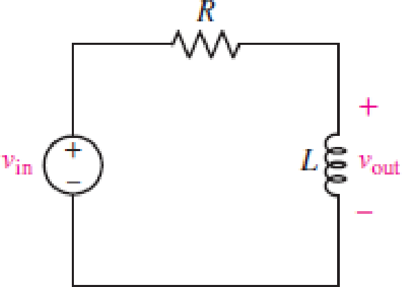
For the RL circuit in Fig. 15.52, (a) determine the transer function defined as H(jω) = vout/vin; (b) for the case of R = 200 Ω and L = 5 mH, construct a plot of the magnitude and phase as a function of frequency; and (c) evaluate the magnitude and phase at a frequency of 10 kHz.
FIGURE 15.52
(a)
Find the transfer function
Answer to Problem 1E
The transfer function
Explanation of Solution
Given data:
Refer to Figure 15.52 in the textbook.
Formula used:
Write the expression to calculate the impedance of the passive elements resistor and inductor.
Here,
Calculation:
The given RL circuit is drawn as Figure 1.
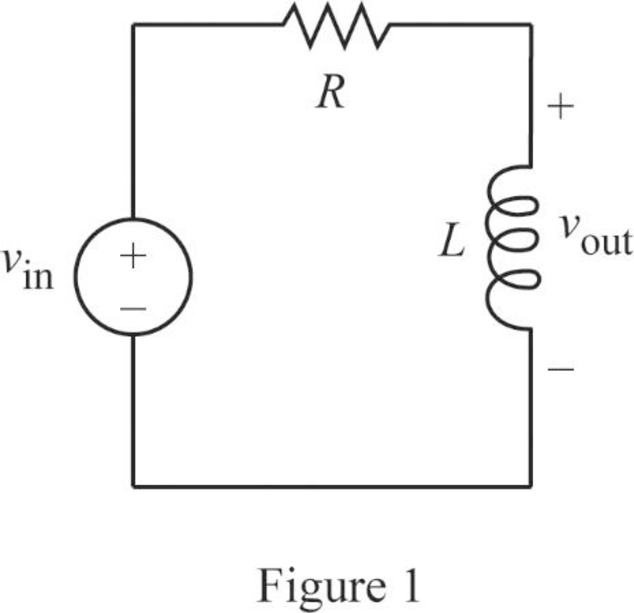
The Figure 1 is redrawn as impedance circuit in Figure 2 using the equations (1) and (2).
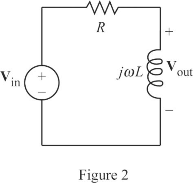
Write the general expression to calculate the transfer function of the circuit in Figure 2.
Here,
Apply Kirchhoff’s voltage law on Figure 2 to find
Rearrange the above equation to find
Substitute
Conclusion:
Thus, the transfer function
(b)
Plot the magnitude and phase as a function of frequency.
Explanation of Solution
Given data:
The value of the resistor
The value of the inductor
Calculation:
From part (a), the transfer function is,
Substitute
Simplify the above equation to find
Re-write the transfer function
From equation (4), the magnitude function of
Write the above equation in decibel (dB).
From equation (4), the phase angle is expressed as follows:
Substitute
Substitute
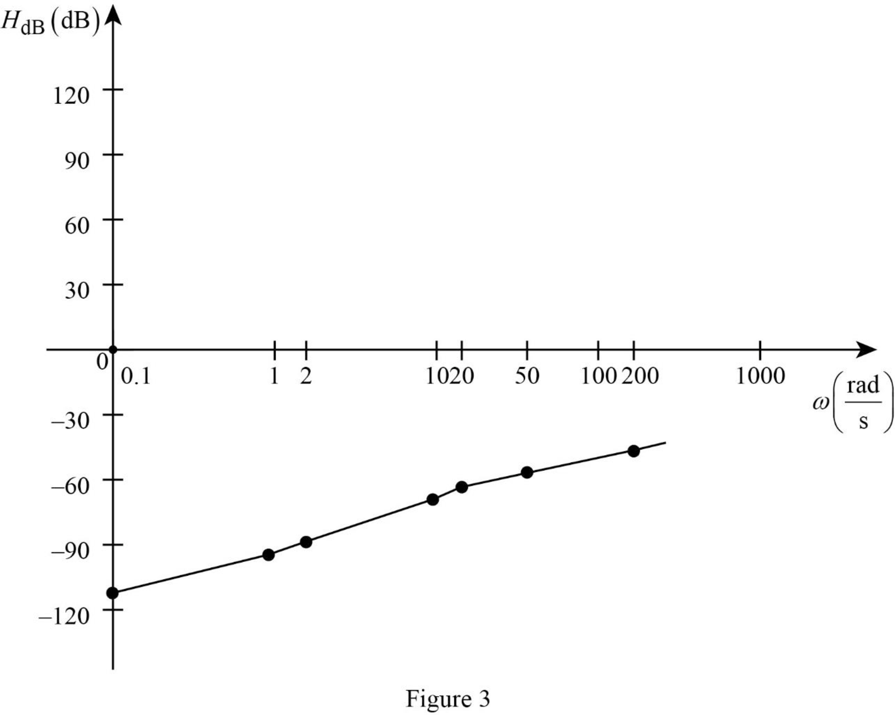
Similarly, by substituting various values for
Table 1
| 0.1 | 1 | 2 | 10 | 20 | 50 | 200 | |
| –112 | –92 | –86 | –72 | –66 | –58 | –46 |
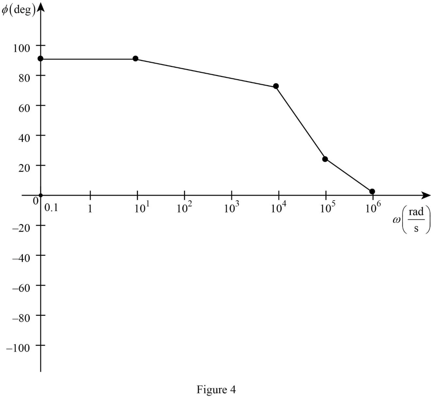
Table 2
| 0.1 | 10 | 104 | 105 | 106 | |
| 90 | 90 | 75.96 | 21.8 | 2.3 |
The Figure 1 is the magnitude plot of the given transfer function obtained using Table 1.
The Figure 2 is the phase plot of the given transfer function obtained using Table 2.
Conclusion:
Thus, the magnitude and phase as a function of frequency is plotted.
(c)
Find the value of the magnitude and phase at a frequency of
Answer to Problem 1E
The value of the magnitude and phase at a frequency of
Explanation of Solution
Given data:
The value of the frequency
Formula used:
Write the expression to calculate the angular frequency.
Here,
Calculation:
From part (a), the transfer function is expressed as,
From equation (7), the magnitude function is expressed as,
Substitute
Substitute
From equation (7), the phase function is expressed as,
Substitute
Substitute
Conclusion:
Thus, the value of the magnitude and phase at a frequency of
Want to see more full solutions like this?
Chapter 15 Solutions
Loose Leaf for Engineering Circuit Analysis Format: Loose-leaf
Additional Engineering Textbook Solutions
ELECTRICITY FOR TRADES (LOOSELEAF)
Fundamentals of Electric Circuits
Introductory Circuit Analysis (13th Edition)
Electric Circuits (10th Edition)
Fundamentals of Applied Electromagnetics (7th Edition)
Basic Engineering Circuit Analysis


- A series RLC network has R = 1.5 KQ, L = 50 mH, and C = 1 microF. Calculate the impedance (in ko) at resonance. (Use 1 decimal place. Unit is not required.)arrow_forwardA series circuit with R = 10 2, L = 0.1 H and C = %3D %3D %3D 50 µF has an applied voltage V = 50 L0° with a variable frequency. Find the resonant frequency, the value of frequency at which maximum voltage occurs across the inductor and the value of fre- quency at which maximum voltage occurs across the сараcitor.arrow_forwardHelp plz: Design a Wein bridge oscillator to generate a sinusoidal waveform of frequency 5KHz.arrow_forward
- 7. Given the following particulars: R, = 40 N, Rc= 20 N, L = 0.254 H, C = 40 µF. Calculate: %3D %3D a. the resonant frequency. b. the frequency in resonance if R_ = Rc suppose that L and C remain unchanged. %3Darrow_forwardA 15.9-uF capacitor and a 15.1-mH inductor are connected in parallel. In series with these units are a variable resistor R and an adjustable reactive device X. joined inseries. (a) Determine the kind and size of device X inductance in henrys orcapacitance in μF) when the circuit is connected to a 50-volf 400-cycle source and is adjusted to resonance. (b) For the resonant condition calculate the value of R if the voltage drop across the paralleled units is to be 100 V.arrow_forwardQ. For the circuit shown, calculate the upper critical frequency due to the input and output circuits. Vcc +20 V Rc C3 2.2 ΚΩ Bae = 150 Cpe = 4 pF Che = 10 pF %3D R %3D 33 kn 0.1 µF RL 5.6 kN R 0.1uF 50 N R2 4.7 kn RE 560 n 10 uFarrow_forward
- In a series RLC circuit that is operating above the resonant frequency, the current Leads the applied voltage Lags the applied voltage Is zero Is in phase with the applied voltage The mathematical relation between impedance and admittance locus are Mirrored Reciprocally O Opposite Inversely The non-sinusoidal waves which represent a sum of infinite number of harmonic waves can affect on All-of-them Electronic Devices and Circuits Power system Communications هذا السؤال مطلوبarrow_forwardProblem Solving Coverage: BJT Small Signal Analysis Instruction: WRITE the complete solutions and box your final answer. Use three (3) decimal places in your final answer. For the figure below: H 6.8 µF Determine the following: B. AC Analysis: www ww 68 kf 16 k2 16 V 2.2kQ 4. Solve the value of Zi, Zo, Av and Ai 2. Solve for re 3. Derive the equation of Zi, Zo, Av and Ai 0.75 k 6.8 µF H 3-100 10 µF 5.6 karrow_forwardFor the series RLC circuit shown, the frequency of the voltage source v, 20cos(@ol) V is adjusted until the resonant frequency (oo) is reached. Under this resonance condition, the inductive reactance X is 38Q and the maximum amplitude of the current i is 2.5 A. The resonant frequency in kHz is R ww I's + 0.1uF O A. 263.16 O B. 1653.47 O C 41.88 O D. 41882.88arrow_forward
- Derive and plot the magnitude and phase responses of the first order difference system, y[n] = x[n]–x[n − 1]. ..arrow_forwardPlot the magnitude and phase plot for the following transfer function, use the templates from the class notes module so as to provide somewhat an accurate representation of the magnitude and phase plots. H (ju) 10 jw (0.01jw+1) (0.1jw+1)arrow_forwardConsider a circuit described by a frequency response represented by the red dotted line in the figure shown. If the input is = 7 cos(27 * 200t) V, what is amplitude of Vout (t)? Vin (t) 8 6 -4 -6 10 20 30 50 100 200 300 500 1000 Frequency (Hz) 4.42 V O 8.81 V O 5.56 V O 7.0 V Question 2 Gain (dB)arrow_forward
 Introductory Circuit Analysis (13th Edition)Electrical EngineeringISBN:9780133923605Author:Robert L. BoylestadPublisher:PEARSON
 Delmar's Standard Textbook Of ElectricityElectrical EngineeringISBN:9781337900348Author:Stephen L. HermanPublisher:Cengage Learning
 Programmable Logic ControllersElectrical EngineeringISBN:9780073373843Author:Frank D. PetruzellaPublisher:McGraw-Hill Education
 Fundamentals of Electric CircuitsElectrical EngineeringISBN:9780078028229Author:Charles K Alexander, Matthew SadikuPublisher:McGraw-Hill Education
 Electric Circuits. (11th Edition)Electrical EngineeringISBN:9780134746968Author:James W. Nilsson, Susan RiedelPublisher:PEARSON
 Engineering ElectromagneticsElectrical EngineeringISBN:9780078028151Author:Hayt, William H. (william Hart), Jr, BUCK, John A.Publisher:Mcgraw-hill Education,