
Concept explainers
Videos
The current waveform depicted in Fig. 2.29 is characterized by a period of 4 s. (a) What is the average value of the current over a single period? (b) Compute the average current over the interval 1 < t < 3 s. (c) If q(0) = 1C, sketch q(t), 0 < t < 4 s.
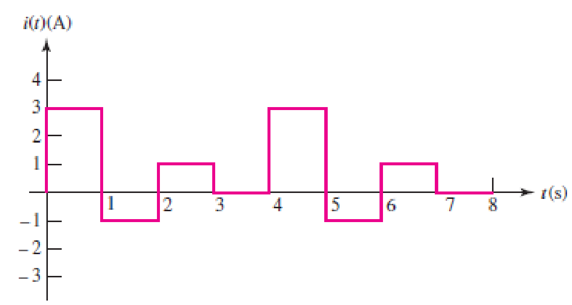
FIGURE 2.29 An example of a time-varying current.
(a)
Find the average value of the given current waveform in Figure 2.29 over the period of 4 s.
Answer to Problem 21E
The average value of the given current waveform over the period of 4 s is
Explanation of Solution
Given data:
Refer to Figure 2.29 in textbook for the time-varying current with the period of 4 s.
Formula used:
Write the formula to find the average value of a function of current over a period as,
Here,
T is the time period.
Calculation:
From the given current waveform in Figure 2.29, the function of current
For the period of
For the period of
For the period of
For the period of
Therefore, the final function of current
The average value of current
Reduce the equation as follows.
Conclusion:
Thus, the average value of the given current waveform over the period of 4 s is
(b)
Find the average current of the waveform over the period of
Answer to Problem 21E
The average current of the waveform over the period of
Explanation of Solution
Given data:
Refer to part (a).
Formula used:
Write the formula to find the average value of a function of current over a period of
Here,
Calculation:
Write the function of current
Now, the average current of
Conclusion:
Thus, the average current of the waveform over the period of
(c)
Sketch the waveform for the charge
Explanation of Solution
Given data:
Refer to part (a).
The initial charge
Formula used:
Write the expression for the relation between charge
Integrate the above equation on both sides.
Calculation:
Using the function of
For
Substitute 3 A for
Substitute 1 C for
Substitute 1 for
For
For the period of
Substitute –1 A for
Substitute 4 C for
Substitute 2 for
For
For the period of
Substitute 1 A for
Substitute 3 C for
Substitute 3 for
For
For the period of
Substitute 0 A for
Substitute 4 C for
Therefore, the charge
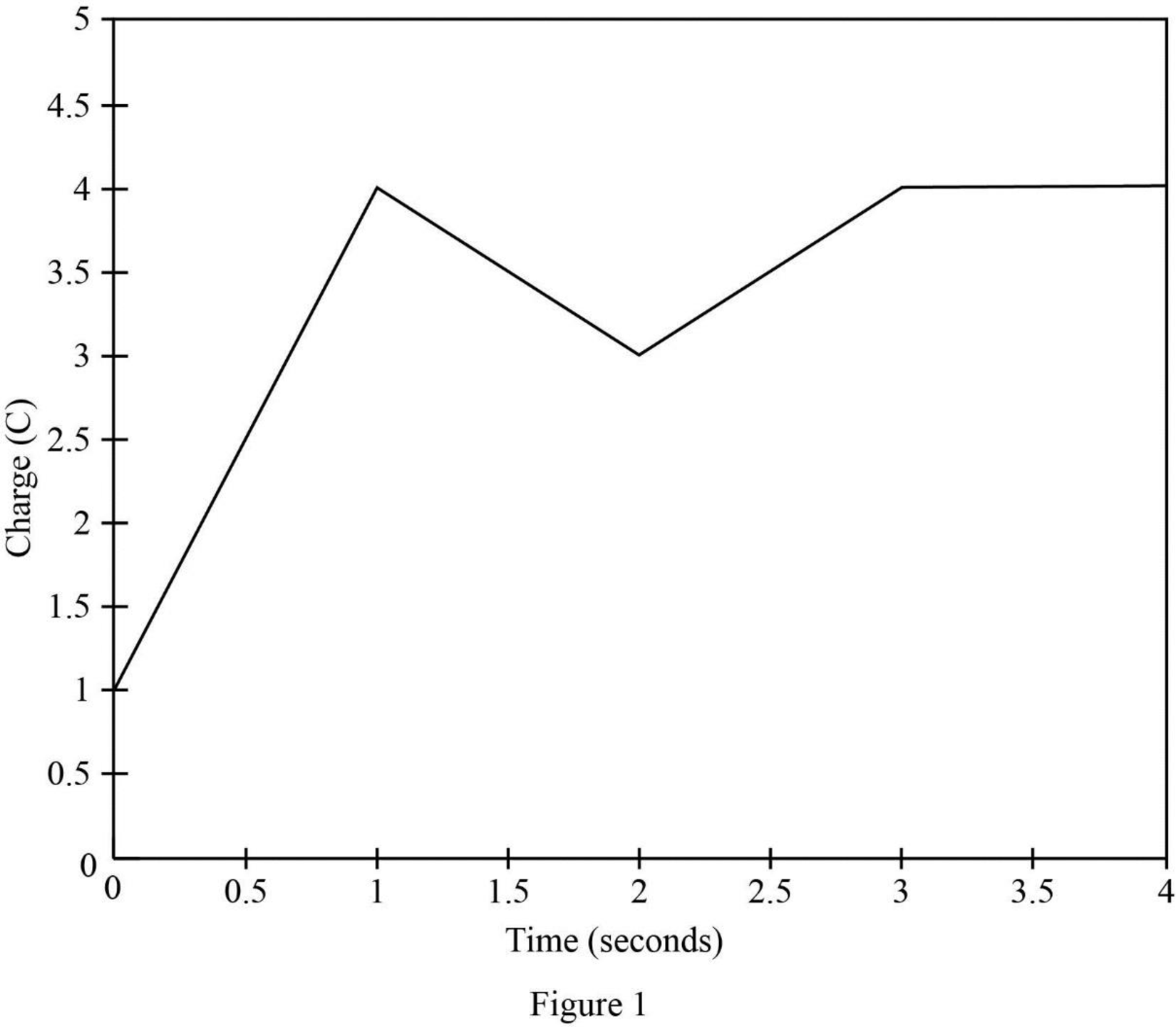
Table 1 shows for
Table 1
| t in seconds | |
| 0 | 1 |
| 1 | 4 |
| 2 | 2 |
| 3 | 4 |
| 4 | 4 |
Figure 1 shows the charge (C) vs time (s) waveform.
Conclusion:
Thus, the waveform for the charge
Want to see more full solutions like this?
Chapter 2 Solutions
Loose Leaf for Engineering Circuit Analysis Format: Loose-leaf


- A single phase bridge rectifier supplied from a 120V - 50 Hz sinusoidal source is connected to an inductive load. The general expression of the RMS AC component of the current is given below where Vm is the maximum input voltage. If R = 1k2, then the value of the inductance that would limit the AC component IAc to less than 5% of the DC component Ipc would be equal to: 4Vm IAC V2. 1. R2 + (2wL)? Select one: O a. 4.92H Ob. 11.92H O c. 8.92H O d. 14.92H TOSHIBA 24arrow_forward2. Build the circuit below shown in Figure 2. R1 1k V1 VOFF = 0 VAMPL = 4W FREQ = 10kHz C1 0.1uF Figure 2 2.3 Plot the waveform v for the voltage across R in simulation. Save the waveform and add it 2.4 Assuming the waveform of the voltage drop across R1 is Vr= VrPCOSwt, determine the amplitude (VRP, in 'Volt') and the radian frequency (w, in 'rad/sec') from the waveform.arrow_forwardQ3] Design a circuit to produce an average voltage of 27V across a 102 load resistor from a 70V rms 50-Hz ac source. Verify your answer by the following: a) Draw the circuit. b) Draw to scale the waveforms for the input, output voltages and the current.arrow_forward
- It is defined as the ratio of rms load voltage and average load voltage of an alternating current. Your answer In electronics it is define as the ratio of the RMS (root mean square) value to the average value (mathematical mean of absolute values of all points on the waveform). Your answer By definition: It is the amount of rms value of ac component to the dc component in the rectifier output. Your answer It is defined as ratio of dc power available at the load to the input ac power. Your answerarrow_forwardhow to do the resizing of elements for the design of a PIEZOELECTRIC TILE PROTOTYPE FOR THE GENERATION OF ELECTRIC ENERGY THROUGH FOOTPASS TRAFFICarrow_forwardA single phase bridge rectifier supplied from a 120V - 50 Hz sinusoidal source is connected to an inductive load. The general expression of the RMS AC component of the current is given below where Vm is the maximum input voltage. If R = 500 Q and L = 1H, then the current ripple factor RF, would be equal to: 4Vm IAc = V2. r. R2 + (2wL)² Select one: O a. 1 O b. 0.8 O C. 0.5 O d. 0.29 TOSHIBAarrow_forward
- Exe: The single-phase bridge rectifier has an RL Load and an ac source, with R = 10Ω andL = 10mH. The peak value of the source is Vm = 100V at 60 Hz. The expressions of voltage andcurrent outputs are:(a) Determine v0(t) and i0(t) with two ac terms (n=2 and 4)(b) Determine the power absorbed by the load.arrow_forwardIn the circuit below, if the inductance L is large enough to operate in continuous current mode. a) Draw the waveform of the output voltage and mains current for the 45 degree trigger angle when the switch S is in transmission. b) Average value of output DA voltage VDC1 when switch S is open, output DA when switch S is closed (in transmission) If the average value of the voltage is VDC2, calculate the value of VDC1 / VDC2. Lesson: power electronics please quickarrow_forwardAttempt five questions only Q1.) a) Derive the basic S.I units, then write the basic dimensions for this expression: R RC R: resistance C: capacitance b) What will be the output of the following meters, if true form factor is (1.32)? where : angular frequency HW.R FW.R DArsoaval PMMC meter meter PSI MIC neler reter Read 4.56Varrow_forward
- Q2 (a) () What is the difference between a Wheatstone bridge and a Kelvin bridge? Your explanation should include suitable diagrams and applications. (ii) Figure Q2a(ii) shows an AC bridge and the meter indicates zero reading. Find the equation for R, from the real part of the impedance Figure Q2a(1) (i) Given that the value for the resistors R. R. R. are 100 02, 250 £2 and 300 1, respectively. The capacitors C, and Care 1 uF and 0.5 µF, respectively. Calculate the resistor. Rarrow_forwardQ1) For the network in a. Find the mathematical expression for the voltage across the capacitor after the switch is thrown into position 1. b. Repeat part (a) for the current ic. c. Find the mathematical expressions for the voltage ve and current ic if the switch is thrown into position 2 at a time equal to five time constants of the charging circuit. d. Plot the waveforms of v and ic for a period of time extending from t 0 to t = 30 µs. %3D 2. E 80 V C 10 pF Ve R2 390 k2 R1 100 k2arrow_forwardAn alternating voltage is represented by the expression v = 35 sin (314.2 t) volt. Determine, i) the maximum value, ii) the frequency, iii) the period of the waveform, and iv) the value 3.5 ms after it passes through zero, going positive. (b) i. Explain the types of semiconductors and the classifications of the semiconductor materials. ii. With the aid of a diagram, explain the formation of the P and N types of semiconductor.arrow_forward
 Introductory Circuit Analysis (13th Edition)Electrical EngineeringISBN:9780133923605Author:Robert L. BoylestadPublisher:PEARSON
 Delmar's Standard Textbook Of ElectricityElectrical EngineeringISBN:9781337900348Author:Stephen L. HermanPublisher:Cengage Learning
 Programmable Logic ControllersElectrical EngineeringISBN:9780073373843Author:Frank D. PetruzellaPublisher:McGraw-Hill Education
 Fundamentals of Electric CircuitsElectrical EngineeringISBN:9780078028229Author:Charles K Alexander, Matthew SadikuPublisher:McGraw-Hill Education
 Electric Circuits. (11th Edition)Electrical EngineeringISBN:9780134746968Author:James W. Nilsson, Susan RiedelPublisher:PEARSON
 Engineering ElectromagneticsElectrical EngineeringISBN:9780078028151Author:Hayt, William H. (william Hart), Jr, BUCK, John A.Publisher:Mcgraw-hill Education,