
Concept explainers
Videos
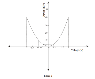
Sketch the power absorbed by a 100 Ω resistor as a function of voltage over the range −2 V ≤ Vresistor ≤ + 2 V.
Sketch the power absorbed by
Explanation of Solution
Given data:
The value of resistor is
The range of voltage is
Formula used:
The expression for power across resistor is as follows.
Here,
The expression for power across resistor is as follows.
Here,
The expression for power across resistor is as follows.
Here,
The expression for power across resistor is as follows.
Here,
The expression for power across resistor is as follows.
Here,
The expression for power across resistor is as follows.
Here,
The expression for power across resistor is as follows.
Here,
The expression for power across resistor is as follows.
Here,
Calculation:
Substitute
Substitute
Substitute
Substitute
Substitute
Substitute
Substitute
Substitute
The plot for the power absorbed by
Conclusion:
Thus, the sketch of the power absorbed by
Want to see more full solutions like this?
Chapter 2 Solutions
Loose Leaf for Engineering Circuit Analysis Format: Loose-leaf


- 1) Consider the circuit shown. Calculate the potential difference across each resistor and the current through each resistor. 50,0 Q 100.0 Q 9.0V 50.0 Q 150.0 Qarrow_forwardSuppose a 10.0 ohm resistor is connected to an emf source to make a closed circuit. If the source has emf = 15.0 V with an internal resistance r = 0.5 ohms, which of the following correctly compares the voltage drop across the emf source and the attached resistor? O a. Voltage drop across emf source is directly proportional to the external resistor O b. Voltage drop across emf source is greater than external resistor O c. Voltage drop across emf source is less than external resistor O d. Voltage drop is the same for the emf source and the external resistor O e. None of the abovearrow_forwardRenewable Energy Systems Homework 2 One type of PV module consists of 72 cells and the size of each cell is 0.125 m x 0.125 m. Theelectricity conversion efficiency of the module under standard test conditions is 14%. Estimate thepower output of one module and the number of modules required to generate 3 kW power at 962W/m2 insolation and 60oC cell temperature, assuming that the temperature coefficient of themodule power is 0.5%/oC. I'm preparing for the exam. Solutions requiredarrow_forward
- Consider the circuit below. The battery has an emf of ℇ = 30.00 V and an internalresistance of r = 1.00 Ω.a. Find the equivalent resistance of the circuit and the current out of the battery.b. Find the terminal voltage of the battery. c. Find the current through each resistor. d. Find the potential difference across each resistor. e. Find the power dissipated by each resistor. f. Find the total power supplied by the battery.arrow_forwardFind the Vpeak of the Vout Value of the circuit below during the positive half cycle. V2 Silicon () 8 R1 V1 AC 24 V3 6 Voutarrow_forward5.) Find the hot resistance of a light bulb rate 60 W, 120 V. 6.) When the voltage across a resistor is 120 V, the current through it is 2.5 mA. Calculate its conductance. 7.) Calculate the current i in the figure when the switch is in position 1 and in position 2. 1 2 100 Q 150 2 3 V +1arrow_forward
- Find the Vpeak of the Vout Value of the circuit below during the negative half cycle. R1 Germanium R Silicon V1 AC 45 V3 8 Voutarrow_forwardThe equivalent resistance of the resistive network shown below is a 50 TA 109 100 50 50 bow Ο α. 200 0b.52 O c. 152 O d. 102 www. www 100arrow_forward2. Determine the equivalent resistance between the terminals a and b 452 352 C0.6662 0.61 0.33352 boarrow_forward
- For solar energy, thermal conversion can be evaluated by the figure of merit. The figure of merit is large if: Select one: O a. both the temperature and the change of temperature are high O b. None of them O c. Only the change of temperature is high O d. Only the temperature is higharrow_forwardReferring to figure shown below, determine the following: a. Total Resistance (R₁) b. Current Ix c. Power at 2009 + 220V 1000 www 1000 1500 www 1000 www 1000 1500 www 1000 lx www 2000arrow_forward1:-9 . .Micr عرض تقدیمي من New 2 Q/Determine the voltage across each resistor in the circuit of figure below. 1.0 kn i mA R 2.2 k 1.5 kn s60 0 II >arrow_forward
 Introductory Circuit Analysis (13th Edition)Electrical EngineeringISBN:9780133923605Author:Robert L. BoylestadPublisher:PEARSON
 Delmar's Standard Textbook Of ElectricityElectrical EngineeringISBN:9781337900348Author:Stephen L. HermanPublisher:Cengage Learning
 Programmable Logic ControllersElectrical EngineeringISBN:9780073373843Author:Frank D. PetruzellaPublisher:McGraw-Hill Education
 Fundamentals of Electric CircuitsElectrical EngineeringISBN:9780078028229Author:Charles K Alexander, Matthew SadikuPublisher:McGraw-Hill Education
 Electric Circuits. (11th Edition)Electrical EngineeringISBN:9780134746968Author:James W. Nilsson, Susan RiedelPublisher:PEARSON
 Engineering ElectromagneticsElectrical EngineeringISBN:9780078028151Author:Hayt, William H. (william Hart), Jr, BUCK, John A.Publisher:Mcgraw-hill Education,