
Concept explainers
Videos
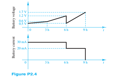
The charge cycle shown in Figure P2.4 is an example of a three-rate charge. The current is held constant at 30 mA for 6 h. Then it is switched to 20 mA for the next 3 h. Find:
a. The total charge transferred Lo the battery.
b. The energy transferred to the battery.
Hint: Recall that energy w is the integral of power, or
(a)
The total charge transferred to the battery.
Answer to Problem 2.4HP
The total charge delivered to the battery is
Explanation of Solution
Calculation:
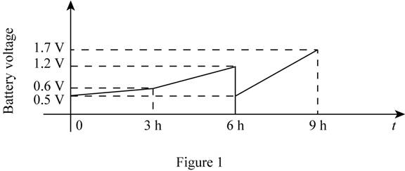
The given diagram for the battery voltage graph is shown below.
The given diagram is shown in Figure 1
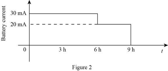
The given diagram for the battery current is shown in Figure 2
The conversion of
The conversion of
The conversion of
The conversion of
The conversion of
The conversion of
The expression for the current for the entire cycle is given by,
The formula for the charge delivered to the battery is calculated as,
Solve further as,
Conclusion:
Therefore, the total charge delivered to the battery is
(b)
The energy that is transferred to the battery.
Answer to Problem 2.4HP
The total power delivered to the battery is
Explanation of Solution
Calculation:
The line equations for the points that joins the point
The line equations for the points that joins the point
The line equations for the points that joins the point
The evaluated value of the battery voltage for different cycles is shown below,
The formula to calculate power supplied by the battery is given by,
Substitute
Substitute
Substitute
The formula for the relation between the power delivered and the energy stored is given by,
The powered delivered to the battery is calculated as,
Conclusion:
Therefore, the total power delivered to the battery is
Want to see more full solutions like this?
Chapter 2 Solutions
Principles and Applications of Electrical Engineering


- a) Find and explain the Ohm conservation expression.b) Stable current circulation is desired for the lamp connected in a circuit to light. Accordingly, discuss with the conservation law of the charge how a stable current circulation can occur from any part of the circuit.I need to explain the answers to these questions, please can you explain in detail. Thanks in advance.arrow_forwardMid-term exam Principles of Electricity (cont'd) 11. According to Ohm's Law, electron flow is proportional to electrical pressure. a. Inversely b. Indirectly c. Directly d. Not 12. What equation represents the characteristics of electron flow in a parallel circuit? a. E=IxR b. ET=E1=E2=E3... c. IT=l1+l2+l3... d. ET=E1+E2+E3... 13. What equation represents the characteristics of electrical pressure in a parallel circuit? a. E=IxR b. ET=E1=E2=E3... c. IT=l1+l2+l3... d. ET=E1+E2+E3.. 14. How much electrical pressure would be required to produce 25A current in a circuit with 19.20 total resistance? a. 480A b. 480V C. 1.3V d. 0.768V 15. As resistors are removed from a series circuit, what will happen to the current? a. The current will increase b. The current will decrease c. The current will stay the same d. There is not enough information givenarrow_forwardThe charging scheme used in Figure is calleda tapered-current charge cycle. The current starts atthe highest level and then decreases with time for theentire charge cycle, as shown. The battery is chargedfor 12 h. Find:a. The total charge delivered to the battery.b. The energy transferred to the battery during thecharging cycle.arrow_forward
- In the circuit in the figure, the value of the current I1 is found as ……….. µA (microampere).arrow_forwardIn the figure the ideal batteries have emfs ɛ1 = 20.4 V, ɛ2 = 9.05 V, and ɛ3 = 5.40 V, and the resistances are each 2.40 Q. What are the (a) size and (b) direction (left or right) of current i,? (c) Does battery 1 supply or absorb energy, and (d) what is its power? (e) Does battery 2 supply or absorb energy, and (f) what is its power? (g) Does battery 3 supply or absorb energy, and (h) what is its power? (a) Number i Units (b) (c) (d) Number i Units (e) (f) Number i Units (g) (h) Number i Unitsarrow_forwardFor the circuit shown in Figure P1.77, solve for the current i x. What types of sources are present in this circuit?arrow_forward
- A practical voltmeter has an internal resistance rm.What is the value of rm if the meter reads 11.81 Vwhen connected as shown in Figure P2.75.arrow_forwardroblem 2. (a) Find the equivalent resistance between point a and point b in figure below. (b) If the potential drop between point and point b is 12.0 V, find the current in the 12.0 resistor.arrow_forwardQuestion 5 a) i. A piece of pencil lead is connected in series with an ammeter and a power supply. The power supply is turned on. After a few minutes, although the potential difference across the pencil lead does not change, the current in the circuit increases significantly. Explain why the current increases. The current /in a length of aluminum of cross-sectional area A is given by the formula I= nevA ii. e is the charge on an electron. Show that the units on the left-hand side of the equation are consistent with those on the right-hand side.arrow_forward
- Figure 2.1 shows a simple circuit. Explain why using a DMM tomeasure the DC voltage across resistor R2 might lead to inaccurate results. Include in your answer how the value of R2 might affect the size of the error and provide some circuit diagrams and equations to showhow to calculate the error.arrow_forwardConsider the circuit shown in Figure P1.64. Use Ohm’s law, KVL, and KCL to find V x.arrow_forwardThe references for the voltage and current at the terminals of acircuit element are as shown . The numerical values for v and i are −20 V and −5 A. Do the electrons gain or lose energy as they pass through theelement in the box?arrow_forward
 Introductory Circuit Analysis (13th Edition)Electrical EngineeringISBN:9780133923605Author:Robert L. BoylestadPublisher:PEARSON
 Delmar's Standard Textbook Of ElectricityElectrical EngineeringISBN:9781337900348Author:Stephen L. HermanPublisher:Cengage Learning
 Programmable Logic ControllersElectrical EngineeringISBN:9780073373843Author:Frank D. PetruzellaPublisher:McGraw-Hill Education
 Fundamentals of Electric CircuitsElectrical EngineeringISBN:9780078028229Author:Charles K Alexander, Matthew SadikuPublisher:McGraw-Hill Education
 Electric Circuits. (11th Edition)Electrical EngineeringISBN:9780134746968Author:James W. Nilsson, Susan RiedelPublisher:PEARSON
 Engineering ElectromagneticsElectrical EngineeringISBN:9780078028151Author:Hayt, William H. (william Hart), Jr, BUCK, John A.Publisher:Mcgraw-hill Education,