
Concept explainers
Videos
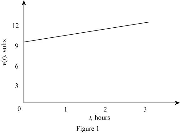
A car battery kept in storage in the basement needs recharging, lf he voltage and the current provided bythe charger during a charge cycle are shown in Figure P2.8,
a. Find the total charge transferred to the battery.
b. Find the total energy transferred to the battery.
(a)
The total charge transferred to the battery.
Answer to Problem 2.8HP
The total charge delivered to the battery is
Explanation of Solution
Calculation:
The given diagram for the battery voltage graph is shown below.
The given diagram is shown in Figure 1
The given diagram for the battery current is shown in Figure 2.
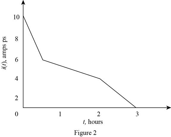
The current equation for the time interval
The current equation for the time interval
The current equation for the time interval
The conversion of
The conversion of
The conversion of
The conversion of c into
The charge delivered to the battery is given by,
Substitute
Conclusion:
Therefore, the total charge delivered to the battery is
(b)
The energy that is transferred to the battery.
Answer to Problem 2.8HP
The total energy delivered to the battery is
Explanation of Solution
Calculation:
The voltage equation of
The formula to calculate the energy is given by,
The energy delivered to the battery for the time period
Substitute
Substitute
Substitute
The formula for the total energy transferred to the battery is given by,
Substitute
Conclusion:
Therefore, the total energy delivered to the battery is
Want to see more full solutions like this?
Chapter 2 Solutions
Principles and Applications of Electrical Engineering


- Note that the charge Q all came from the power supply through the resistor ) During the chargingthe power delivered by the supply is P = IV The energy delivered by the supply is powerxtime, or since lis varying during charging E=V int I dt=VQ since I is just charge per time. Compute the energy E = VQ delivered by the supply and compare with the energy of the fully-charged capacitorWhat happened to the rest of the energy? %3D Transient RC response. Consider the following circuit with R-1 k2, C=0.1 µF and V-10 Volts. Initially the capacitor is discharged (Vc-0) and the switch is open as shown, so no current flows. At time t-0 the switch is closed, allowing current to flow through the resistor and charge up the capacitor. Rarrow_forwardIn the figure the ideal batteries have emfs ɛ1 = 20.4 V, ɛ2 = 9.05 V, and ɛ3 = 5.40 V, and the resistances are each 2.40 Q. What are the (a) size and (b) direction (left or right) of current i,? (c) Does battery 1 supply or absorb energy, and (d) what is its power? (e) Does battery 2 supply or absorb energy, and (f) what is its power? (g) Does battery 3 supply or absorb energy, and (h) what is its power? (a) Number i Units (b) (c) (d) Number i Units (e) (f) Number i Units (g) (h) Number i Unitsarrow_forwardMid-term exam Principles of Electricity (cont'd) 11. According to Ohm's Law, electron flow is proportional to electrical pressure. a. Inversely b. Indirectly c. Directly d. Not 12. What equation represents the characteristics of electron flow in a parallel circuit? a. E=IxR b. ET=E1=E2=E3... c. IT=l1+l2+l3... d. ET=E1+E2+E3... 13. What equation represents the characteristics of electrical pressure in a parallel circuit? a. E=IxR b. ET=E1=E2=E3... c. IT=l1+l2+l3... d. ET=E1+E2+E3.. 14. How much electrical pressure would be required to produce 25A current in a circuit with 19.20 total resistance? a. 480A b. 480V C. 1.3V d. 0.768V 15. As resistors are removed from a series circuit, what will happen to the current? a. The current will increase b. The current will decrease c. The current will stay the same d. There is not enough information givenarrow_forward
- The circuit below(left) displays a schematic diagram of a battery. The voltage measured by U1 is called the terminal voltage given R1 = 1 ohm. In the circuit below(right), the terminal voltage of each of the battery-resistor combination is VT = 1.5 volts. Find the voltage across R1 & voltage of the battery. Find the percentage of voltage loss of the battery due to the internal resistance R1.arrow_forwardsketch vL1 and vR2 on a graph. mark the labels in microseconds one time constant after the charging phase begins and the value of each voltage at that timearrow_forward3. The figure on the left below shows a schematic diagram of a battery. The voltage measured by U1 is called the terminal voltage given R1 = 1 ohm. In the figure on the right below, the terminal voltage of each of the battery-resistor combination is Vr = 1.5 volts. Find the following: a. The current passing through R5. b. The currents passing through R1 and R3 C. The voltage across R1. d. The voltage of the battery EMF. e. The percentage of voltage loss ot the battery due to the internal resistance R1. The power dissipated by the internal resistance R1. g. The power dissipated by R5 if R1 = R2 = R3 = R4 = 0. h. The percentage of power dissipation loss due to the four resistors R1, R2, R3, and R4 f. R1 R3 S10 R1 U1 1.500 EMF EMF R5 100 V1 R2 $10 EMF R4 EMF EMFarrow_forward
- A practical voltmeter has an internal resistance rm.What is the value of rm if the meter reads 11.81 Vwhen connected as shown in Figure P2.75.arrow_forwardDetermine the nodes/junctions, Current (I), Loops, Voltage drop on each Resistor (R), and Power (P) on each Resistor (R) with the following given and illustration: Use the following given for batteries and resistors (color bands for your value of resistors, use the lower limit). R1 = red red black goldR2 = orange green black silverR3 = white orange black goldR4 = green violet brown goldR5 = violet red black silverR6 = yellow green black silverR7 = brown black black gold V1 (lower left) = 100VV2 (top center) = 150VV3 (lower right) = 200Varrow_forwardSteady current circulation is desired for a lamp connected in a circuit to light. For this, explain how a stable current will occur from any part of the circuit with the conservation law of the charge. Give me detail pls.arrow_forward
- Figure 2.1 shows a simple circuit. Explain why using a DMM tomeasure the DC voltage across resistor R2 might lead to inaccurate results. Include in your answer how the value of R2 might affect the size of the error and provide some circuit diagrams and equations to showhow to calculate the error.arrow_forwardThe circuit below(left) displays a schematic diagram of a battery. The voltage measured by U1 is called the terminal voltage given R1 = 1 ohm. In the circuit below(right), the terminal voltage of each of the battery-resistor combination is VT = 1.5 volts. Find the voltage across R1 & voltage of the battery.arrow_forwardA circuit delivers energy at the rate of 20 W and the current is 10 A. Determine the energy of each coulomb of charge in the circuit .arrow_forward
 Introductory Circuit Analysis (13th Edition)Electrical EngineeringISBN:9780133923605Author:Robert L. BoylestadPublisher:PEARSON
 Delmar's Standard Textbook Of ElectricityElectrical EngineeringISBN:9781337900348Author:Stephen L. HermanPublisher:Cengage Learning
 Programmable Logic ControllersElectrical EngineeringISBN:9780073373843Author:Frank D. PetruzellaPublisher:McGraw-Hill Education
 Fundamentals of Electric CircuitsElectrical EngineeringISBN:9780078028229Author:Charles K Alexander, Matthew SadikuPublisher:McGraw-Hill Education
 Electric Circuits. (11th Edition)Electrical EngineeringISBN:9780134746968Author:James W. Nilsson, Susan RiedelPublisher:PEARSON
 Engineering ElectromagneticsElectrical EngineeringISBN:9780078028151Author:Hayt, William H. (william Hart), Jr, BUCK, John A.Publisher:Mcgraw-hill Education,