
Physics for Scientists and Engineers: Foundations and Connections
1st Edition
ISBN: 9781133939146
Author: Katz, Debora M.
Publisher: Cengage Learning
expand_more
expand_more
format_list_bulleted
Videos
Textbook Question
Chapter 29, Problem 81PQ
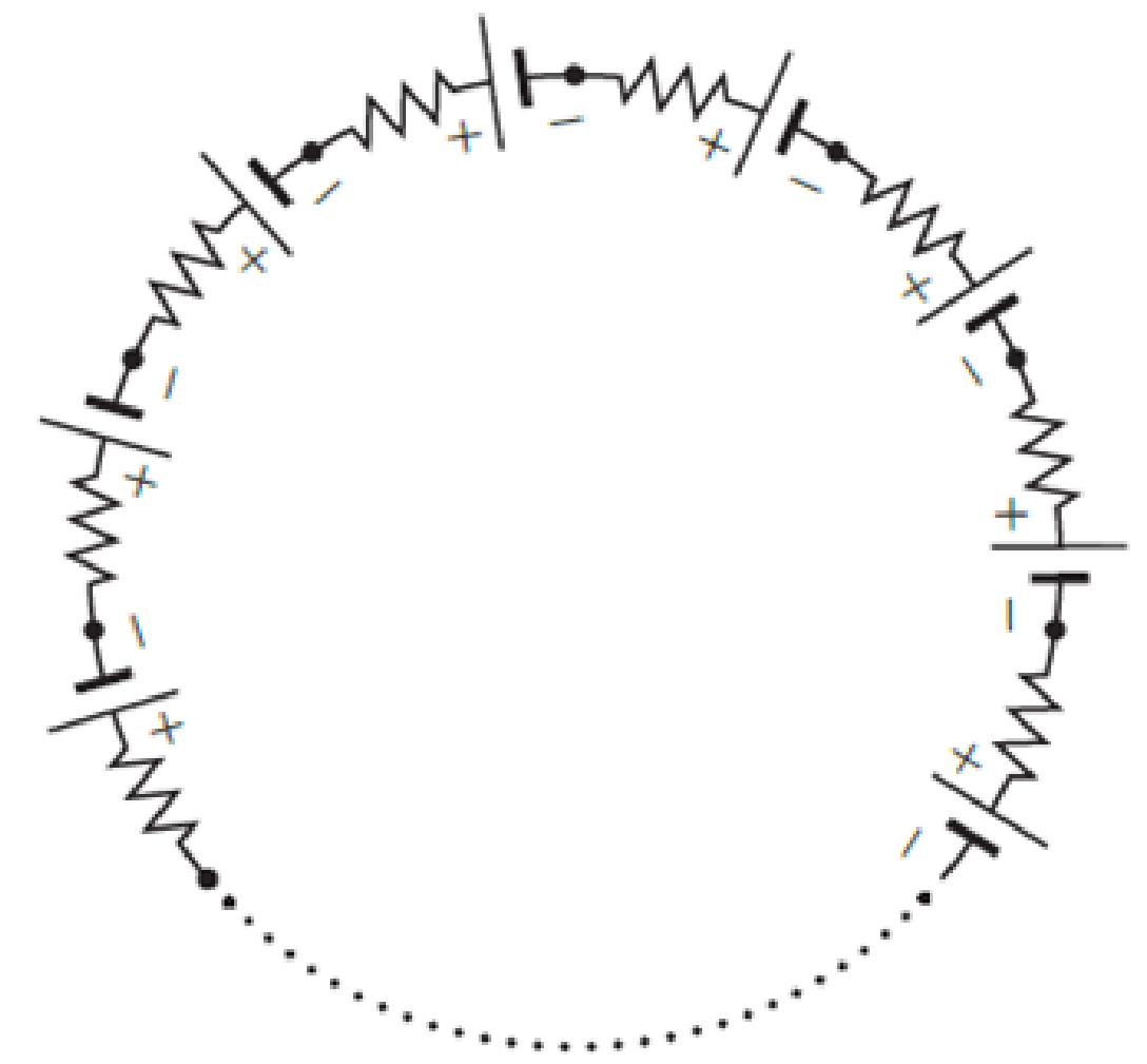
In Figure P29.81, N real batteries, each with an emf ε and internal resistance r, are connected in a closed ring. A resistor R can be connected across any two points of this ring, causing there to be n real batteries in one branch and N – n resistors in the other branch. Find an expression for the current through the resistor R in this case.
Expert Solution & Answer
Want to see the full answer?
Check out a sample textbook solution
Students have asked these similar questions
A 2 µF capacitor is connected to two resistors and a 10 V battery, as shown. Both switches A and B are open initially, and the capacitor is uncharged. Switch A is now closed. After a few
seconds A is opened and after that B is closed. Just after B is closed what is the current through the 10 ohm resistor?
A
B
10 2
10 V
2 µF
WW
zero
O 1.0 A
O 2.0 A
O 0.63 A
O 0.37 A
25.54. In the circuit shown in
Fig. P25.54, R is a variable resistor whose
value ranges from 0 to co, and a and b are
the terminals of a battery that has an emf
E = 15.0V and an internal resistance of
4.00 2. The ammeter and voltmeter are
idealized meters. As R varies over its full
range of values, what will be the largest
and smallest readings of (a) the voltmeter
and (b) the ammeter? (c) Sketch qualita-
tive graphs of the readings of both meters
as functions of R.
Figure P25.54
R
You have a battery with a voltage of Vtotal = 25 V and two resistors, both with a resistance of R, = R,
%3D
40 0.
a. How can you connect the resistors to the battery (in series or parallel) in order to achieve the
largest power dissipation? How much power is dissipated in this case?
Chapter 29 Solutions
Physics for Scientists and Engineers: Foundations and Connections
Ch. 29.1 - What are the SI units of ?Ch. 29.1 - Prob. 29.2CECh. 29.2 - Prob. 29.3CECh. 29.4 - Prob. 29.5CECh. 29.4 - Prob. 29.6CECh. 29.5 - Prob. 29.7CECh. 29 - Study the symbols in Table 29.2. Then, without...Ch. 29 - Prob. 2PQCh. 29 - Prob. 3PQCh. 29 - Suppose you need to measure the potential...
Ch. 29 - Prob. 5PQCh. 29 - Prob. 6PQCh. 29 - A real battery (modeled as an ideal emf device in...Ch. 29 - Prob. 8PQCh. 29 - Two circuits made up of identical ideal emf...Ch. 29 - Prob. 10PQCh. 29 - Prob. 11PQCh. 29 - Prob. 12PQCh. 29 - Eight real batteries, each with an emf of 5.00 V...Ch. 29 - Prob. 14PQCh. 29 - Prob. 15PQCh. 29 - Prob. 16PQCh. 29 - Prob. 17PQCh. 29 - Prob. 18PQCh. 29 - Prob. 19PQCh. 29 - An ideal emf device with emf is connected to two...Ch. 29 - Prob. 21PQCh. 29 - Prob. 22PQCh. 29 - Prob. 23PQCh. 29 - Prob. 24PQCh. 29 - Prob. 25PQCh. 29 - Prob. 26PQCh. 29 - Determine the currents through the resistors R2,...Ch. 29 - The emf devices in the circuits shown in Figure...Ch. 29 - Prob. 29PQCh. 29 - Prob. 30PQCh. 29 - Prob. 31PQCh. 29 - Prob. 32PQCh. 29 - Prob. 33PQCh. 29 - Prob. 34PQCh. 29 - A Figure P29.35 shows a combination of six...Ch. 29 - A Each resistor shown in Figure P29.36 has...Ch. 29 - Each resistor shown in Figure P29.36 has a...Ch. 29 - Prob. 38PQCh. 29 - Prob. 39PQCh. 29 - The emf in Figure P29.40 is 4.54 V. The...Ch. 29 - Figure P29.41 shows three resistors (R1 = 14.0 ,...Ch. 29 - Figure P29.42 shows five resistors and two...Ch. 29 - The emfs in Figure P29.43 are 1 = 6.00 V and 2 =...Ch. 29 - Prob. 44PQCh. 29 - Figure P29.45 shows five resistors connected...Ch. 29 - Figure P29.46 shows a circuit with a 12.0-V...Ch. 29 - Two ideal emf devices are connected to a set of...Ch. 29 - Two ideal emf devices are connected to a set of...Ch. 29 - Three resistors with resistances R1 = R/2 and R2 =...Ch. 29 - Prob. 51PQCh. 29 - Prob. 52PQCh. 29 - Prob. 53PQCh. 29 - Prob. 55PQCh. 29 - At time t = 0, an RC circuit consists of a 12.0-V...Ch. 29 - A 210.0- resistor and an initially uncharged...Ch. 29 - Prob. 58PQCh. 29 - A real battery with internal resistance 0.500 and...Ch. 29 - Figure P29.60 shows a simple RC circuit with a...Ch. 29 - Prob. 61PQCh. 29 - Prob. 62PQCh. 29 - Prob. 63PQCh. 29 - Ralph has three resistors, R1, R2, and R3,...Ch. 29 - Prob. 65PQCh. 29 - An ideal emf device is connected to a set of...Ch. 29 - Prob. 67PQCh. 29 - An ideal emf device (24.0 V) is connected to a set...Ch. 29 - Prob. 69PQCh. 29 - What is the equivalent resistance between points a...Ch. 29 - A capacitor with initial charge Q0 is connected...Ch. 29 - Prob. 73PQCh. 29 - Prob. 74PQCh. 29 - Prob. 75PQCh. 29 - Prob. 76PQCh. 29 - Figure P29.77 shows a circuit with two batteries...Ch. 29 - In the RC circuit shown in Figure P29.78, an ideal...Ch. 29 - Prob. 79PQCh. 29 - Calculate the equivalent resistance between points...Ch. 29 - In Figure P29.81, N real batteries, each with an...Ch. 29 - Prob. 82PQCh. 29 - Prob. 83PQCh. 29 - Prob. 84PQCh. 29 - Figure P29.84 shows a circuit that consists of two...Ch. 29 - Prob. 86PQCh. 29 - Prob. 87PQCh. 29 - Prob. 88PQCh. 29 - Prob. 89PQCh. 29 - Prob. 90PQCh. 29 - Prob. 91PQCh. 29 - Prob. 92PQCh. 29 - Prob. 93PQCh. 29 - Prob. 94PQCh. 29 - Prob. 95PQ
Knowledge Booster


Learn more about
Need a deep-dive on the concept behind this application? Look no further. Learn more about this topic, physics and related others by exploring similar questions and additional content below.Similar questions
- Eight real batteries, each with an emf of 5.00 V and an internal resistance of 0.200 , are connected end to end in a loop as in Figure P29.13. What is the terminal voltage across one of the batteries between points a and b?arrow_forwardA student makes a homemade resistor from a graphite pencil 5.00 cm long, where the graphite is 0.05 mm indiameter. The resistivity of the graphite is =1.38102/m . The homemade resistor is place inseries with a switch, a 10.00-mF capacitor and a 0.50-V power source, (a) What is the BC time constant of the circuit? (b) What is the potential drop across the pencil 1.00 s after the switch is closed?arrow_forwardFigure P29.45 shows five resistors connected between terminals a and b. a. What is the equivalent resistance of this combination of resistors? b. What is the current through each resistor if a 24.0-V battery is connected across the terminals?arrow_forward
- Two ideal emf devices are connected to a set of resistors as shown in Figure P29.47. If 1 = 6.00 V, R1 = 10.00 , R2 = 5.00 , R3 = 15.00 , R4 = 20.00 , and the current through R4 is 0.250 , what is the emf 2?arrow_forwardWhat is the equivalent resistance between points a and b of the six resistors shown in Figure P29.70? FIGURE P29.70arrow_forwardAn ideal emf device (24.0 V) is connected to a set of resistors as shown in Figure P29.66. If R1 = 22.5 , R2 = 52.5 , R3 = 125 , and R4 = 75.0 , what is the voltage drop across each resistor?arrow_forward
- Each resistor shown in Figure P29.36 has a resistance of 100.0 . An ideal emf device (120.0 V) is connected to points a and b via two leads (not shown in the figure). Find the current that flows through the emf device.arrow_forwardThe figure displays two circuits with a charged capacitor that is to be discharged through a resistor when a switch is closed. In figure (a) below, R₁ = 21.7 Q and C₁ = 5.08 µF. In figure (b) below, R₂ = 10.5 Q and C₂ = 8.00 μF. The ratio of the initial charges on the two capacitors is 902/901 = 1.82. At time t = 0, both switches are closed. At what time t do the two capacitors have the same charge? Number i 0.188 Units 00 ms (a) (b)arrow_forwardE2 R1 R2 2. Find the charge on the capacitor after the switch has been left open for some time, then closed for some period of time. We can assume that C = 2 µF, with batteries of values E1 = 2V and E2 = 1 V, and resistor values R1 R2 = 0.25 2. 0.52 andarrow_forward
- A 400 µF capacitor is connected through a resistor to a battery. Find (a) the resistance R and (b) the emf of the battery if the time constant of the circuit is 0.5 s and the maximum charge on the capacitor is 0.024 C. O a. R = 1350 0, e = 80 V O b. R = 1250 0, E = 60 V O C. R = 1200 Q, e = 80 V O d. R = 1150 Q, e = 60 Varrow_forwardR C 3. From the figure above, a switch is closed at time t = 0, allowing the capacitor to begin charging. The capacitance of the capacitor is given a value of C = 10 µF with a resistor of resistance R= 10N. At what time is the potential across the capacitor equal to the potential across the resistor?arrow_forwardIn a heart pacemaker, a pulse is delivered to the heart 84 times per minute. The capacitor that controls this pulsing rate discharges through a resistance of 3.9 ✕ 106 Ω. One pulse is delivered every time the fully charged capacitor loses 63.2% of its original charge. What is the capacitance of the capacitor? Farrow_forward
arrow_back_ios
arrow_forward_ios
Recommended textbooks for you
 Physics for Scientists and Engineers: Foundations...PhysicsISBN:9781133939146Author:Katz, Debora M.Publisher:Cengage Learning
Physics for Scientists and Engineers: Foundations...
Physics
ISBN:9781133939146
Author:Katz, Debora M.
Publisher:Cengage Learning
DC Series circuits explained - The basics working principle; Author: The Engineering Mindset;https://www.youtube.com/watch?v=VV6tZ3Aqfuc;License: Standard YouTube License, CC-BY