
Physics for Scientists and Engineers: Foundations and Connections
1st Edition
ISBN: 9781133939146
Author: Katz, Debora M.
Publisher: Cengage Learning
expand_more
expand_more
format_list_bulleted
Videos
Textbook Question
Chapter 29, Problem 85PQ
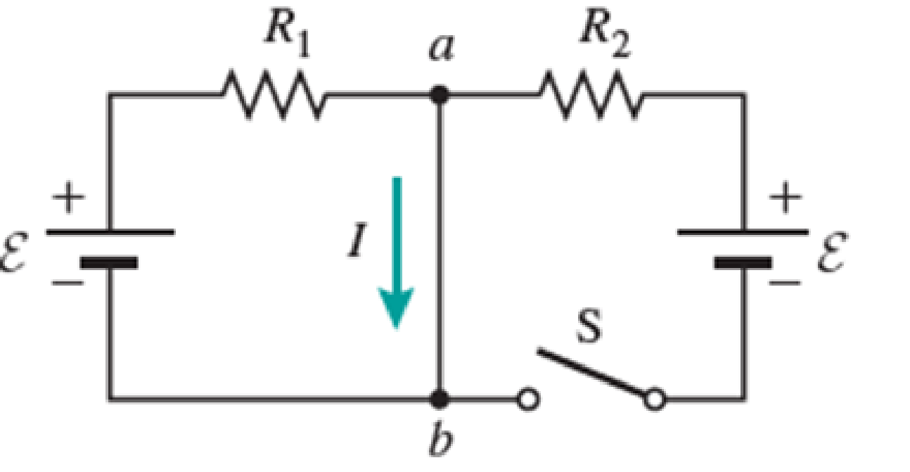
Figure P29.84 shows a circuit that consists of two identical emf devices. If R1 = R2 = R and the switch is closed, find an expression (in terms of R and ε) for the current I that is in the branch from point a to b.
Expert Solution & Answer

Trending nowThis is a popular solution!

Students have asked these similar questions
Chapter 32, Problem 018
Your answer is partially correct. Try again.
The circuit in the figure consists of switch S, a 4.50 V ideal battery, a 35.0 M2 resistor, and an airfilled capacitor. The capacitor has
parallel circular plates of radius 5.10 cm, separated by 1.50 mm. At time t = 0, switch S is closed to begin charging the capacitor. The
electric field between the plates is uniform. At t = 160 µs, what is the magnitude of the magnetic field within the capacitor, at radial
distance 3.30 cm?
S
R
Number
Units
Use correct number of significant digits; the tolerance is +/-1 in the 3rd significant digit
Chapter 32, Problem 018
Your answer is partially correct. Try again.
The circuit in the figure consists of switch S, a 4.50 V ideal battery, a 35.0 M2 resistor, and an airfilled capacitor. The capacitor has
parallel circular plates of radius 5.10 cm, separated by 1.50 mm. At time t = 0, switch S is closed to begin charging the capacitor. The
electric field between the plates is uniform. At t = 160 µs, what is the magnitude of the magnetic field within the capacitor, at radial
distance 3.30 cm?
C
S
R
Number
Units
T.
Use correct number of significant digits; the tolerance is +/-1 in the 3rd significant digit
In the figure ɛ1 = 6.88 V, ɛ2 = 12.7 V, R1 = 96.3 Q, R2 = 180 Q, and R3 = 318 Q. One point of the circuit is grounded (V = 0). What are the
(a) size and (b) direction (up or down) of the current through resistance 1, the (c) size and (d) direction (left or right) of the current
through resistance 2, and the (e) size and (f) direction of the current through resistance 3? (g) What is the electric potential at point A?
R2
Chapter 29 Solutions
Physics for Scientists and Engineers: Foundations and Connections
Ch. 29.1 - What are the SI units of ?Ch. 29.1 - Prob. 29.2CECh. 29.2 - Prob. 29.3CECh. 29.4 - Prob. 29.5CECh. 29.4 - Prob. 29.6CECh. 29.5 - Prob. 29.7CECh. 29 - Study the symbols in Table 29.2. Then, without...Ch. 29 - Prob. 2PQCh. 29 - Prob. 3PQCh. 29 - Suppose you need to measure the potential...
Ch. 29 - Prob. 5PQCh. 29 - Prob. 6PQCh. 29 - A real battery (modeled as an ideal emf device in...Ch. 29 - Prob. 8PQCh. 29 - Two circuits made up of identical ideal emf...Ch. 29 - Prob. 10PQCh. 29 - Prob. 11PQCh. 29 - Prob. 12PQCh. 29 - Eight real batteries, each with an emf of 5.00 V...Ch. 29 - Prob. 14PQCh. 29 - Prob. 15PQCh. 29 - Prob. 16PQCh. 29 - Prob. 17PQCh. 29 - Prob. 18PQCh. 29 - Prob. 19PQCh. 29 - An ideal emf device with emf is connected to two...Ch. 29 - Prob. 21PQCh. 29 - Prob. 22PQCh. 29 - Prob. 23PQCh. 29 - Prob. 24PQCh. 29 - Prob. 25PQCh. 29 - Prob. 26PQCh. 29 - Determine the currents through the resistors R2,...Ch. 29 - The emf devices in the circuits shown in Figure...Ch. 29 - Prob. 29PQCh. 29 - Prob. 30PQCh. 29 - Prob. 31PQCh. 29 - Prob. 32PQCh. 29 - Prob. 33PQCh. 29 - Prob. 34PQCh. 29 - A Figure P29.35 shows a combination of six...Ch. 29 - A Each resistor shown in Figure P29.36 has...Ch. 29 - Each resistor shown in Figure P29.36 has a...Ch. 29 - Prob. 38PQCh. 29 - Prob. 39PQCh. 29 - The emf in Figure P29.40 is 4.54 V. The...Ch. 29 - Figure P29.41 shows three resistors (R1 = 14.0 ,...Ch. 29 - Figure P29.42 shows five resistors and two...Ch. 29 - The emfs in Figure P29.43 are 1 = 6.00 V and 2 =...Ch. 29 - Prob. 44PQCh. 29 - Figure P29.45 shows five resistors connected...Ch. 29 - Figure P29.46 shows a circuit with a 12.0-V...Ch. 29 - Two ideal emf devices are connected to a set of...Ch. 29 - Two ideal emf devices are connected to a set of...Ch. 29 - Three resistors with resistances R1 = R/2 and R2 =...Ch. 29 - Prob. 51PQCh. 29 - Prob. 52PQCh. 29 - Prob. 53PQCh. 29 - Prob. 55PQCh. 29 - At time t = 0, an RC circuit consists of a 12.0-V...Ch. 29 - A 210.0- resistor and an initially uncharged...Ch. 29 - Prob. 58PQCh. 29 - A real battery with internal resistance 0.500 and...Ch. 29 - Figure P29.60 shows a simple RC circuit with a...Ch. 29 - Prob. 61PQCh. 29 - Prob. 62PQCh. 29 - Prob. 63PQCh. 29 - Ralph has three resistors, R1, R2, and R3,...Ch. 29 - Prob. 65PQCh. 29 - An ideal emf device is connected to a set of...Ch. 29 - Prob. 67PQCh. 29 - An ideal emf device (24.0 V) is connected to a set...Ch. 29 - Prob. 69PQCh. 29 - What is the equivalent resistance between points a...Ch. 29 - A capacitor with initial charge Q0 is connected...Ch. 29 - Prob. 73PQCh. 29 - Prob. 74PQCh. 29 - Prob. 75PQCh. 29 - Prob. 76PQCh. 29 - Figure P29.77 shows a circuit with two batteries...Ch. 29 - In the RC circuit shown in Figure P29.78, an ideal...Ch. 29 - Prob. 79PQCh. 29 - Calculate the equivalent resistance between points...Ch. 29 - In Figure P29.81, N real batteries, each with an...Ch. 29 - Prob. 82PQCh. 29 - Prob. 83PQCh. 29 - Prob. 84PQCh. 29 - Figure P29.84 shows a circuit that consists of two...Ch. 29 - Prob. 86PQCh. 29 - Prob. 87PQCh. 29 - Prob. 88PQCh. 29 - Prob. 89PQCh. 29 - Prob. 90PQCh. 29 - Prob. 91PQCh. 29 - Prob. 92PQCh. 29 - Prob. 93PQCh. 29 - Prob. 94PQCh. 29 - Prob. 95PQ
Knowledge Booster


Learn more about
Need a deep-dive on the concept behind this application? Look no further. Learn more about this topic, physics and related others by exploring similar questions and additional content below.Similar questions
- Three resistors with resistances R1 = R/2 and R2 = R3 = R are connected as shown, and a potential difference of 225 V is applied across terminals a and b (Fig. P29.49). a. If the resistor R1 dissipates 75.0 W of power, what is the value of R? b. What is the total power supplied to the circuit by the emf? c. What is the potential difference across each of the three resistors?arrow_forwardYou connect a battery, resistor, and capacitor as in (Figure 1), where E = 46.0 V, C = 5.00 μF, and R = 130 Ω. The switch S is closed at t = 0. When the voltage across the capacitor is 8.00 VV, what is the magnitude of the current in the circuit? At what time tt after the switch is closed is the voltage across the capacitor 8.00 V? When the voltage across the capacitor is 8.00 V, at what rate is energy being stored in the capacitor?arrow_forwardIn the circuit diagram below, the switch S is closed for a long time (which means that the capacitor C is fully charged, and so there will be no current in the capacitor's branch of the circuit). In the figure, Vo = 12 V, R₁ = 22 R₂ = 42 and C = 1 μF. S I R₂ R₁ C a) What is the voltage across R₁ (when C is fully charged) ? b) What is the voltage across C (when C is fully charged)? c) The switch S is now opened. What is the current through R₁ as a function of time, t?arrow_forward
- A current of I = 4.7 A passes through the circuit shown, where R = 46 Q. I 3R 5R ww ww 2R 6R §2RR ww 10R 5R A. In terms of R, I, and numeric values, write an expression for the voltage of the source, V. B. What is the voltage, V in volts?arrow_forwardThe capacitor in the circuit shown below is initially uncharged. The switch is closed at t = 0 s. AVbattery = 24 V, C = 3.0 μF, and R = 2.0 Q. At sometime after the switch is closed, the voltage across the resistor is measured to be 16 V. What is the charge on the capacitor at this time, in µC? Your answer needs to have 2 significant figures, including the negative sign in your answer if needed. Do not include the positive sign if the answer is positive. No unit is needed in your answer, it is already given in the question statement.arrow_forwardFor the circuit shown in the figure, C = 12 µF and R = 8.5 MΩ. Initially the switch S is open with the capacitor charged to a voltage of 80 V. The switch is then closed at time t = 0.00 s. What is the charge on the capacitor, when the current in the circuit is 3.3 µA?arrow_forward
- The circuit in the figure below contains two resistors, R1 = 2.10 kΩ and R2 = 2.60 kΩ, and two capacitors, C1 = 2.30 µF and C2 = 3.30 µF, connected to a battery with emf = 105 V. There are no charges on the capacitors before switch S is closed. I need help with part a and part b. See image for the original question.arrow_forward78. A In the RC circuit shown in Figure FOR P29.78, an ideal battery with emf CHEST E and internal resistance r is con- no bruta 101 nected to capacitor C. The switch OTU S is initially open and the capacitor noilor is uncharged. At t = 0, the switch 20 is closed. srit word or abs gnizu dmod odi unslaviups 15/vol S ε reutills α.— himmisiob of W+0.000 21 d I f es bspar 21251 in 152 s ban a. Determine the charge q on the capacitor at time t. Tro b. Find the current in the branch b-e at time t. What is the the 1569 € 210121231 910 current as t goes to infinity? 100% www r b e digi Div ST 0 R + 20, 251 29gnado 101000 9.00 V bilov adi tol noia201qzs FIGURE P29.77 5.00 265 Ω www STEVO R www.c FIGURE P29.78 poses. 79. N A 12.0-V battery is used to cho **** 21 memisa M.ET C - - с d b bes 19lbbigarrow_forwardThe switch in the circuit below has been in position a for a long time. At time t = 0 the switch is thrown to position b. You are given the data: Vb = 36 V, C = 8 μF. Vc is the voltage across the capacitor. If the charge on the capacitor at time t = 0.3 msec after the switch is thrown is 54.1 μC, what is the value of the resistor R? a) 89.71 Ω b) 44.86 Ω c) 22.43 Ω d) Not enough information.arrow_forward
- A capacitor with a capacitance of 3.5 μF is initially uncharged. It is connected in series with a switch of negligible resistance, a resistor with a resistance of 19.5 kΩ, and a battery that has a potential difference of 155 V. 1. Immediately after the switch is closed, what is the current, in amperes, through the resistor? 2. Find an expression for the time after the switch is closed when the current in the resistor equals half its maximum value. 3. What is the charge Q, in microcoulombs, on the capacitor when the current in the resistor equals one half its maximum value.arrow_forwardProblem 5: A current of I- 2.6 A passes through the circuit shown, where R- 65 3R 5R V) 2R 6R 2R 7R 5R 10R Otheexpertta.com Part (a) In terms of R, I, and numeric values, write an expression for the voltage of the · source, V. Part (b) What is the voltage, V in volts? tan( sin() cotanO a acos cosh0t cosO asin() acotan 4 5 6 sinh() cotanhO *1 23 0 tanh0c O Degrees O Radians CLEAR BACKSPACEarrow_forwardA circuit with three resistors connected in series and parallel connection with a supply DC voltage is shown in the figure. The supply voltage of, Vsupply=120 V, Resistances R1=100, R2 = 200, R3=300 and R4= 400, R6=190 (R5 is not connected). What will be the magnitude of voltage, Vab between a and b?arrow_forward
arrow_back_ios
SEE MORE QUESTIONS
arrow_forward_ios
Recommended textbooks for you
 Physics for Scientists and Engineers: Foundations...PhysicsISBN:9781133939146Author:Katz, Debora M.Publisher:Cengage Learning
Physics for Scientists and Engineers: Foundations...
Physics
ISBN:9781133939146
Author:Katz, Debora M.
Publisher:Cengage Learning
What is Electromagnetic Induction? | Faraday's Laws and Lenz Law | iKen | iKen Edu | iKen App; Author: Iken Edu;https://www.youtube.com/watch?v=3HyORmBip-w;License: Standard YouTube License, CC-BY