
Concept explainers
Videos
The value of the node voltages
Answer to Problem 3.46HP
The value of node voltage
Explanation of Solution
Calculation:
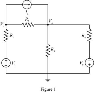
The given diagram is shown in Figure 1
Replace all the voltage sources except source
The required diagram is shown in Figure 2
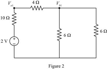
Apply nodal at the node
The expression to calculate the current through the resistance
Substitute
The expression to calculate the value of the voltage
Substitute
Short circuit the source
The required diagram is shown in Figure 3
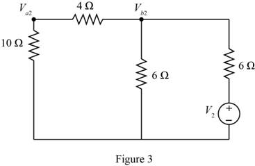
Apply nodal at the node
The value of the voltage
Substitute
Replace all the sources shown in Figure 1 and consider only the current source, then redraw the circuit.
The required diagram is shown in Figure 4
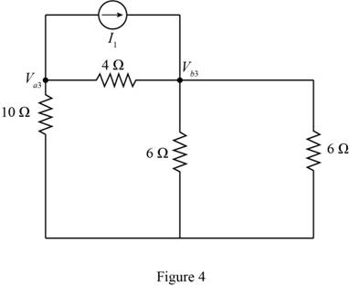
Apply nodal at the node
Apply nodal at the node
From equation (1) and equation (2) the node voltages are,
The expression to calculate the node voltage
Substitute
The expression to calculate the node voltage
Substitute
Conclusion:
Therefore, the value of node voltage
Want to see more full solutions like this?
Chapter 3 Solutions
Principles and Applications of Electrical Engineering


- 3b For the circuit in Figure Q3(b), solve for Ix, Iy and Vz using superposition method.arrow_forward4- In the circuit in following figure, obtain y 1, v2, and v3. 15 V 25 V 10 V 20 Varrow_forward8-13 E (a) Formulate mesh-current equations for the cir- cuit in Figure P3-13. (b) Formulate node-voltage equations for the circuit in Figure P3-13. (c) Which set of equations would be easier to solve? Why? (d) Using MATLAB, find , and i, in terms of the mesh- current variables. SSarrow_forward
- Refer to the given circuit below. Using Superposition Theorem, determine the percent contribution of E₁ to the current through R3 (lbc)- 1 R3E1 % contribution = - x 100 R3E2 + 1 R1 R2 R3 R4 E₁ E2 I 3 Ω 70 4 Ω 3 Ω 7 V 8 V 5 A I R3E1 +1 R31 + R₁ E₁ a ↑ R₂ C b R3 R4 E₂ +arrow_forwardb) For the circuit shown in Figure Q3b: i) Define coupling coefficient. ii) Find the voltage, Vx. j3 2 + Vx -A j4 Q j2 Q 520° V j5 Q j7 Q j1 0 12 12 Q Figure Q3barrow_forwardQ3: Suppose that the components of the circuit shown in figure below have the following values: RI= SkD, R2= 9kΩ, R3-10kΩ , R4-5kΩ, R5-10kΩ, R6-9k Ω. The voltage across AB is measured by a voltmeter whose internal resistance is 95k2. What is the measurement error caused by the resistance of the measuring instrument? R3 Rs RM Ri SMA Fo Em Ry Barrow_forward
- Electrical Engineering I looked that the other explnations were incorrect, so I would like for a better explanation please, especially when people were finding the gain and got it at 13000 (they used +13V in their case) +10 R, 10 k2 Rp 100 k2 +15 Vo Time 20 k2 5 k23W -15 Vô -10 (b) (a) Figure E3.1 (a) This circuit sums the input voltage v plus one-half of the balancing voltage v. Thus the output voltage v, can be set to zero even when v has a nonzero de component, (b) The three waveforms show v, the input voltage; (v + v/2), the balanced-out voltage; and vo, the amplified output voltage. If vy were directly amplified, the op amp would saturate. 3.3 Use the circuit shown in Figure E3.1 to design a de-coupled one-op-amp circuit that will amplify the +100 uV EOG to have the maximal gain possible without exceeding the typical guaranteed linear output range. Include a control that can balance (remove) series clectrode offset potentials up to +300 m V. Give all numerical values. Voltage, Varrow_forwardR1 D1 D2 R2 V1 V3 R3 V2 Rj=120 Q, R2=10 Q and R3=200 2, Vi= 10V and V2=15V, Dị and D2 (forward voltage drop) VF=0.8V a) Using mesh analysis to analyze the given circuit, derive the voltage V3. b) What is the state operation of Di and D2?arrow_forward(b) Prove the circuit in Figure Q.5 can perform the operation of adder/subtractor by completing Table Q.5. -Sub FA FA FA FA Figure Q.5 Table Q.5 B[3:0] Sub A[3:0] C4 S[3:0] Operation 0111 1000 1 0111 1000arrow_forward
- 3.40 Find Vi and V in the circuit shown in Figure P340. FIGURE P3.40 2 kn R2 V2 4 kn 2000 i 5 V 3 kn 2.5 k 45arrow_forwardRefer to the given circuit below. Using Superposition Theorem, determine the percent contribution of I to the current through R3 (lbc). IR31 % contribution = x 100 1 +1 +1 R3E1 "R3E2 R3 R4 E1 E2 I 6Q 1Q 9 V 7V 3A a R31 R1 2Q R1 R2 1Q E₁ R2 C b R3 R4 E2arrow_forwardQ2 – For the circuit shown in the Figure below, use superposition to find “v" in terms of R's and source values. U1 R1 R3 U2 R2.arrow_forward
 Introductory Circuit Analysis (13th Edition)Electrical EngineeringISBN:9780133923605Author:Robert L. BoylestadPublisher:PEARSON
 Delmar's Standard Textbook Of ElectricityElectrical EngineeringISBN:9781337900348Author:Stephen L. HermanPublisher:Cengage Learning
 Programmable Logic ControllersElectrical EngineeringISBN:9780073373843Author:Frank D. PetruzellaPublisher:McGraw-Hill Education
 Fundamentals of Electric CircuitsElectrical EngineeringISBN:9780078028229Author:Charles K Alexander, Matthew SadikuPublisher:McGraw-Hill Education
 Electric Circuits. (11th Edition)Electrical EngineeringISBN:9780134746968Author:James W. Nilsson, Susan RiedelPublisher:PEARSON
 Engineering ElectromagneticsElectrical EngineeringISBN:9780078028151Author:Hayt, William H. (william Hart), Jr, BUCK, John A.Publisher:Mcgraw-hill Education,