
Concept explainers
Videos
Find the Thé venin equivalent resistance seen byresistor
The Thevenin equivalent resistance seen by the resistor
Answer to Problem 3.62HP
The Thevenin equivalent resistance is
Explanation of Solution
Calculation:
The given diagram is shown in Figure 1
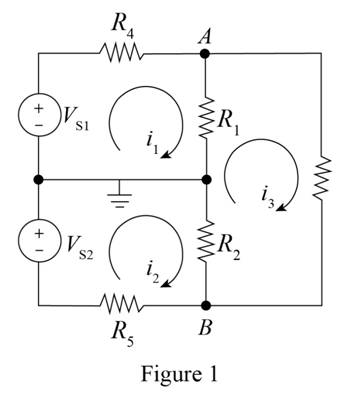
To calculate the value of Thevenin equivalent resistance, short circuit the voltage source and open circuit the current source, open circuit the load resistance
The required diagram is shown in Figure 2
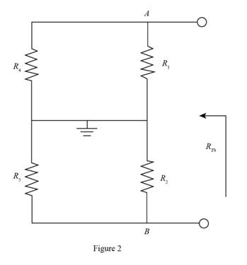
From the above figure the expression for the equivalent resistance of the circuit is evaluated as,
The expression for the Thevenin resistance of the circuit is given by,
Substitute
To calculate the open circuit voltage of the circuit, open circuit the load resistance and redraw the circuit.
The required diagram is shown in Figure 3
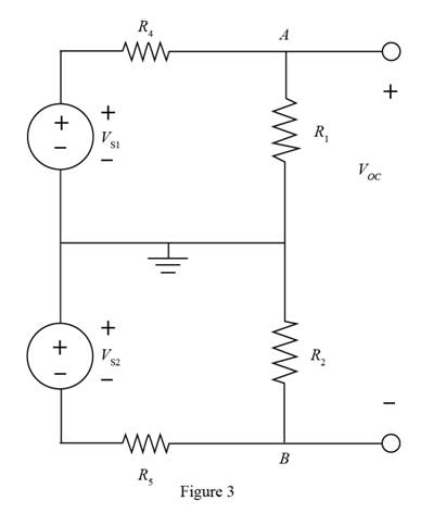
The expression to evaluate the voltage across the resistance
The expression to evaluate the voltage across the resistance
The expression for the open circuit voltage is given by,
Substitute
Mark the values and draw the Thevenin equivalent seen by the loadresistance
The required diagram is shown in Figure 4
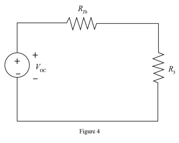
The expression for the Norton equivalent resistance is given by,
Substitute
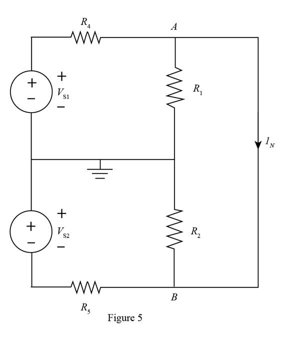
To find the Norton current, short circuit the load resistance and redraw the circuit.
The required diagram is shown in Figure 5
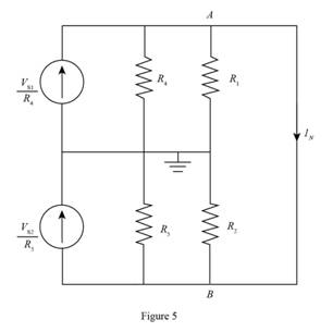
To obtain the Norton current convert the voltage sources of the above circuit into current source and redraw the circuit..
The required diagram is shown in Figure 6
The resistance
The resistance
The expression for the Norton current is given by,
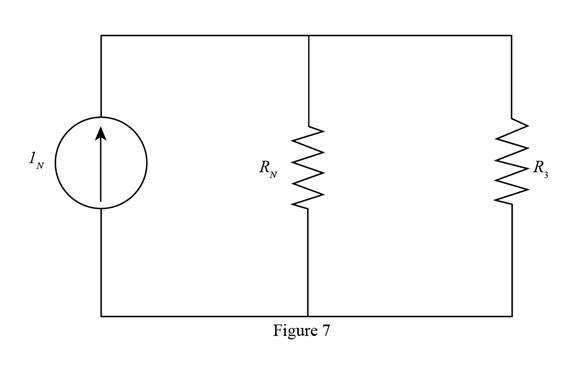
Mark the values and draw the Norton equivalent of the circuit.
The required diagram is shown in Figure 7
Conclusion:
Therefore, the Thevenin equivalent resistance is
Want to see more full solutions like this?
Chapter 3 Solutions
Principles and Applications of Electrical Engineering


- If we have a voltmeter, during the measurement do we need a voltmeter with high or low input impedance to measure current. How about when we need to measure voltage drop. Please explain. ..arrow_forwardA chopper is employed to charge a battery as shown in figure. The charging current is 5 A. The duty ratio is 0.2. The chopper output voltage is also shown in the figure. The peak to peak ripple current in the charging current is https://practicepaper.in/wp-content/uploads/GATE/EE/20031/q87.jpgarrow_forwardQ3. State the main advantages and disadvantages of the dual-slope ADC circuits.arrow_forward
- 4. From the figure shown which is series-parallel, the following values are: ID ohms in series with the parallel combination of 30 and DD ohms respectively. If the supply voltage is bD volts, find the following: a) equivalent resistance b)total current c)individual current d)current at 3D and D ohms onlyarrow_forwardQ3. Draw the output voltage waveform for each circuit including the voltage values. (Ideal model) 2.2 k2 +30 V V. OV -30 V +5 V +50 V 47 3.3 kn -5 V -50 V D 2:1 +100 V -- IN4001 R. V ov 10 k2 -100 V IN4001 Q4. For the following bridge rectifier circuit, draw the output voltage waveform across the load (RL) showing the maximum value. Calculate the following: The average value of the output voltage across the load (RL). a. b. The rms value of the output voltage across the load (RL). c. The average load current. d. The rms value of the load current. (Use constant voltage drop model for the Silicon diode) 5:1 D, o Vrms DA 10 KNarrow_forward3.39. (a) Consider the electronic switch shown in Figure P3.39. Assume ideal diodes, R = RL = 1k2, Vci = +5V, and Vc2 = -5 V. Plot the transfer characteristic (v, versus vin) for Vin ranging from -5 V to +5 V. (b) Repeat for Vci = -5 V and Vc2 = +5 V. RL Vo +. R Vc2arrow_forward
- Explain in details any one application from first order circuit.arrow_forwardWhat is the load current for the circuit shown in the figure? Please choose one: a. 9.0 mA b. 7.5 mA c. 3.0 mA D. 6.0 mAarrow_forwardQ3) V_in Design a regulated circuit to supply a constant voltage of (10 V) across a resistive load of (50 Q). The input 15 V 15 voltage is shown in the figure. The minimum current for the Zener diode operation is (Izk=5mA). Find the maximum power dissipated in the Zener diode. 12.5 12 V 10arrow_forward
- Sketch the output voltage (V,) for the circuit and the input voltage (V;) shown in figure (3).arrow_forward(a) Plot the load line and find the Q-point for the diode circuit shown in P3.53 if V = 5 V and R =10kΩ. Use the i-v characteristic as shown in P3.39. (b) Repeat for V =−6V and R =3kΩ. (c) Repeat for V =−3 V and R = 3kΩ.arrow_forwardQ3) Design a regulated circuit to supply a constant voltage of (10 V) across a resistive load of (50 N). The input 15 V 15 voltage is shown in the figure. The minimum current for the Zener diode operation is (Izk=5mA). Find the maximum power dissipated in the Zener diode. 12.5 12 V 10arrow_forward
 Introductory Circuit Analysis (13th Edition)Electrical EngineeringISBN:9780133923605Author:Robert L. BoylestadPublisher:PEARSON
 Delmar's Standard Textbook Of ElectricityElectrical EngineeringISBN:9781337900348Author:Stephen L. HermanPublisher:Cengage Learning
 Programmable Logic ControllersElectrical EngineeringISBN:9780073373843Author:Frank D. PetruzellaPublisher:McGraw-Hill Education
 Fundamentals of Electric CircuitsElectrical EngineeringISBN:9780078028229Author:Charles K Alexander, Matthew SadikuPublisher:McGraw-Hill Education
 Electric Circuits. (11th Edition)Electrical EngineeringISBN:9780134746968Author:James W. Nilsson, Susan RiedelPublisher:PEARSON
 Engineering ElectromagneticsElectrical EngineeringISBN:9780078028151Author:Hayt, William H. (william Hart), Jr, BUCK, John A.Publisher:Mcgraw-hill Education,