
Videos
4.9 through 4.11 Two vertical forces are applied to a beam of the cross section shown. Determine the maximum tensile and compressive stresses in portion BC of the beam.
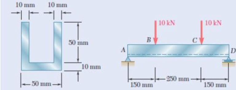
Fig. P4.11
Find the maximum tensile and compressive stresses in portion BC of the beam.
Answer to Problem 11P
The maximum compressive and tensile stress in the in the section BC are
Explanation of Solution
Given information:
Calculation:
Show the cross-section of the beam as shown in figure 1.
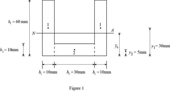
Refer to Figure 1.
Calculate the value of
Substitute
Calculate the moment of inertia
Substitute
The moment of inertia of rectangle 2 is same as the moment of inertia of rectangle 1. Then,
Calculate the moment of inertia
Substitute
Calculate the total moment of inertia (I) of the cross-section as follows:
Substitute
Refer Figure 1.
Consider the distance between the neutral axis and the top fiber and bottom fiber of the beam is
Calculate
Show the section of the beam left of C as shown in Figure 2.
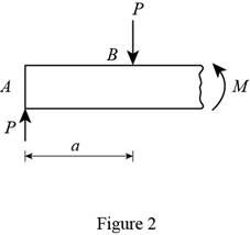
Refer to Figure 2.
Calculate the moment M using the relation:
Substitute
Calculate the value of stress
Substitute
Calculate the value of stress
Substitute
Thus, the maximum compressive and tensile stress in the in the section BC are
Want to see more full solutions like this?
Chapter 4 Solutions
Mechanics of Materials, 7th Edition


- 4.37 A W 200 x 31.3 rolled-steel beam is subjected to a couple M of moment 45 kN-m. Knowing that E= Z00GPA, v=0.29, determine (a) the radius of curvature P. (b) the radius of curvature p' of a transverse cross section. SOLUTIONarrow_forwardM = 500 Nm PROBLEM 4.2 В Knowing that the couple shown acts in the vertical plane, determine the stress at (a) point A, and (b) point B. [Ans. (a) -116.4 MPa (b) -87.3 MPa] 30 mm 40 mm Fig. P4.2arrow_forwardEXERCISE 4.2 1. Three long parallel wires equal in length are supporting a rigid bar connected at their bottoms as shown in Fig. 4.15. If the cross-sectional area of each wire is 100 mm, calculate the stresses in cach wire. Take E, = 100 GPa and E, = 200 GPa. (Ans. o, 25 MPa ; 0, = 50 MPa] 10 kN Fig. 4.15 Brassarrow_forward
- A copper strip (E = 105 GPa) and an aluminum strip (E = 75 GPa) are bonded together to form the composite beam shown. Knowing that the beam is bent about a horizontal axis by a couple of moment M = 35 N.m, determine the maximum stress in (a) the aluminum strip, (b) the copper strip. Fig. P4.39 Aluminum Copper 24 mm 6 mm 6 mmarrow_forwardA 1600-lb-in. couple is applied to a wooden beam, of rectangular cross section 1.5 by 3.5 in., in a plane forming an angle of 308 with the vertical (Fig. ). Determine (a) the maximum stress in the beam and (b) the angle that the neutral surface forms with the horizontal planearrow_forward4.19 and 4.20 Knowing that for the extruded beam shown the allowable stress is 120 MPa in tension and 150 MPa in compres- sion, determine the largest couple M that can be applied. 80 mm- 125 mm 54 mm 50 mm 125 mm 40 mm M Fig. P4.20 150 mm Fig. P4.19 Marrow_forward
- 20 40 20 Dimensions in mm PROBLEM 4.1 20 M = 15 kNm Knowing that the couple 80 shown acts in the vertical plane, determine the stress at (a) point A, and (b) point B. [Ans. (a) -61.2 MPa (b) 91.8 MPa] 20 В Fig. P4.1arrow_forwardSITUATION. Given: a = 1.5 m, b = 1.5 m, L= 2.4 m W В a- Beam properties: I = 198 x 105 mm Rod properties: Diameter = 12 mm E = 200 GPa E = 200 GPa 99. Due to the load, W, rod BC elongates by 1 mm. Find the force (KN) in rod BC which caused the elongation. A. 4.4 В. 6.4 C. 9.4 D. 11.4 100.Due to the load, W, the force developed in rod BC is 12 kN, what is the value of W (kN)? A. 20.47 с. 6 82 D. 24.00 B. 56.33 101.Due to a load, W = 40 kN, the force developed in rod BC = 10 kN. The diameter of rod BC is 16 mm. Find the moment (kN- m) at the fixed end. A. 90 В. 60 C. 45 D. 30arrow_forwardThe member having a rectangular cross-section, Fig. a, is designed to resist a moment of 40 N # m. In order to increase its strength and rigidity, it is proposed that two small ribs be added at its bottom, Fig. b. Determine the maximum normal stress in the member for both cases.arrow_forward
- Fig. 2 4. A steel shaft of diameter 50 mm and length 1.2 m (E = 210 GPa and v = 0.3) is loaded with multiple force system. At a point in the shaft, the state of stress relative to the x, y, z coordinate system was found to be: [600 0 T = 0 320 MPa -480 (a) Draw a cube element showing the stress components on each coordinate face (Hint: No vector lines for zero stresses; Warning: A stress element without reference axes will receive zero point). (b) From the given stress tensor, determine the values of (i) octahedral normal stress (Goct) and (ii) octahedral shear stress (toct). (c) From your answer in (b), determine (i) dilatational strain energy Udilat '); and (ii) deviatoric strain energy (Udist). (d) Find the total strain energy at the point.arrow_forwardAC B P C. Fig. 4.57 Problem Fig. 4.55 Problems 4.7 and 4.8 Problem 4.11 A Problem 4.8 Reconsider the L-shaped beam illustrated in hinged to the wal Fig. 4.55. This time, assume that the applied force P has 2 mmnd it weighs components in the positive x and positive z directions such that P= P,i + Pj. Determine the reactions generated at the fixed end of the beam in terms of a, b, P. and P of the beam and it attached to the bea the horizontal. At t Answers: RA P(-X): RAV 0: RA-P.(-) wall. A load that w such that its gravity bP:(+v): M -a: P(-v): MA -bP.(- load of the same wei nOnt Barrow_forwardThe beam shown is made of a nylon for which the allowable stress is 24 MPa in tension and 30 MPa in compression. Determine the largest couple M that can be applied to the beam. Solve Prob. 4.16, assuming that d = 40 mm. For Problem 4.17, flip the T cross section upside down. Do not reverse the way thecoupleis applied.(a) Determinethe largest coupleMthat can be applied. (b) Determine the largest compressive stress. (c) Determine the largesttensile stress. (d)Replace this beam by another that isrectangularwith the same total area,supportcanhave thesame maximum coupleM.Make acentrally locatedcircular extrusion of diameter:(d1)Determinethe diameter ofthis circle.(d2)Determinethe lengthsof the sidesof thisrectanglearrow_forward
 Elements Of ElectromagneticsMechanical EngineeringISBN:9780190698614Author:Sadiku, Matthew N. O.Publisher:Oxford University Press
 Mechanics of Materials (10th Edition)Mechanical EngineeringISBN:9780134319650Author:Russell C. HibbelerPublisher:PEARSON
 Thermodynamics: An Engineering ApproachMechanical EngineeringISBN:9781259822674Author:Yunus A. Cengel Dr., Michael A. BolesPublisher:McGraw-Hill Education
 Control Systems EngineeringMechanical EngineeringISBN:9781118170519Author:Norman S. NisePublisher:WILEY
 Mechanics of Materials (MindTap Course List)Mechanical EngineeringISBN:9781337093347Author:Barry J. Goodno, James M. GerePublisher:Cengage Learning
 Engineering Mechanics: StaticsMechanical EngineeringISBN:9781118807330Author:James L. Meriam, L. G. Kraige, J. N. BoltonPublisher:WILEY