
Concept explainers
Videos
a)
Show that the maximum compressive stresses are in the ratio 4:5:7:9.
a)
Explanation of Solution
Given information:
The load act on the point of the bars is P.
Calculation:
At the point A:
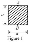
Show the cross-sectional diagram of the square bar as in Figure 1.
Here,
Refer to Figure 1.
The maximum compressive stress of the square bar
Here, e is the eccentricity of the load and
The cross-sectional area of the square bar
The eccentricity of the load (e) is
The distance between the centroid from extreme fibre
The moment of inertia
Calculate the maximum compressive stress of the square bar
Substitute
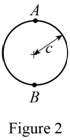
Show the cross-sectional diagram of the circular bar as in Figure 2.
Here,
Refer to Figure 2.
The maximum compressive stress of the circular bar
The cross-sectional area of the circular bar
The eccentricity of the load (e) is
The distance between the centroid from extreme fibre
The moment of inertia
Calculate the maximum compressive stress of the circular bar
Substitute
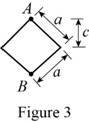
Show the cross-sectional diagram of the diamond shape bar as in Figure 3.
Here,
Refer to Figure 3.
The maximum compressive stress of the diamond shape bar
The cross-sectional area of the diamond shape bar
The eccentricity of the load (e) is
The distance between the centroid from extreme fibre
The moment of inertia
Calculate the maximum compressive stress of the diamond shape bar
Substitute
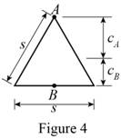
Show the cross-sectional diagram of the triangular bar as in Figure 4.
Here,
Refer to Figure 4.
The maximum compressive stress of the triangular bar
The cross-sectional area of the triangular bar
The distance between the centroid from extreme fibre
The eccentricity of the load (e) is
The moment of inertia
Calculate the maximum compressive stress of the triangular bar
Substitute
Calculate the maximum compressive stresses are in the ratio:
Substitute
The four bars shown have the same cross-sectional area.
Hence the maximum compressive stresses are in the ratio 4:5:7:9 is proved.
b)
Show that the maximum tensile stresses are in the ratio 2:3:5:3.
b)
Explanation of Solution
Given information:
The load act on the point of the bars is P.
Calculation:
At the point B:
Refer to Figure 1.
The maximum tensile stress of the square bar
Here, the e is the eccentricity of the load and
The cross-sectional area of the square bar
The eccentricity of the load (e) is
The distance between the centroid from extreme fibre
The moment of inertia
Calculate the maximum tensile stress of the square bar
Substitute
Refer to Figure 2.
The maximum tensile stress of the circular bar
The cross-sectional area of the circular bar
The eccentricity of the load (e) is
The distance between the centroid from extreme fibre
The moment of inertia
Calculate the maximum tensile stress of the circular bar
Substitute
Refer to Figure 3.
The maximum tensile stress of the diamond shape bar
The cross-sectional area of the diamond shape bar
The eccentricity of the load (e) is
The distance between the centroid from extreme fibre
The moment of inertia
Calculate the maximum tensile stress of the diamond shape bar
Substitute
Refer to Figure 4.
The maximum tensile stress of the triangular bar
The cross-sectional area of the triangular bar
The distance between the centroid from extreme fibre
The eccentricity of the load (e) is
The moment of inertia
Calculate the maximum tensile stress of the triangular bar
Substitute
Calculate the maximum tensile stresses are in the ratio:
Substitute
The four bars shown have the same cross-sectional area.
Hence the maximum tensile stresses are in the ratio 2:3:5:3 is proved.
Want to see more full solutions like this?
Chapter 4 Solutions
Mechanics of Materials, 7th Edition


- M= 500 Nm PROBLEM 4.2 Knowing that the couple shown acts in the vertical plane, determine the stress at (a) point A, and (b) point B. [Ans. (a) -116.4 MPa (b) -87.3 MPa] 30 mm 40 mm Fig. P4.2 E231 hparrow_forwardM = 500 Nm PROBLEM 4.2 В Knowing that the couple shown acts in the vertical plane, determine the stress at (a) point A, and (b) point B. [Ans. (a) -116.4 MPa (b) -87.3 MPa] 30 mm 40 mm Fig. P4.2arrow_forwardEXERCISE 4.2 1. Three long parallel wires equal in length are supporting a rigid bar connected at their bottoms as shown in Fig. 4.15. If the cross-sectional area of each wire is 100 mm, calculate the stresses in cach wire. Take E, = 100 GPa and E, = 200 GPa. (Ans. o, 25 MPa ; 0, = 50 MPa] 10 kN Fig. 4.15 Brassarrow_forward
- 4.17. Determine the components of stress from the results obtained in (a) v=rsin 0, ve = 2r cos 0 (b) VT = cos 0, 1/4 = 0 (c) v = V₁ = 0 (d) v = (1 - 4) cos 0, Ve= - - (1 + 4/4) sin 0 - Barrow_forwardFig. 2 4. A steel shaft of diameter 50 mm and length 1.2 m (E = 210 GPa and v = 0.3) is loaded with multiple force system. At a point in the shaft, the state of stress relative to the x, y, z coordinate system was found to be: [600 0 T = 0 320 MPa -480 (a) Draw a cube element showing the stress components on each coordinate face (Hint: No vector lines for zero stresses; Warning: A stress element without reference axes will receive zero point). (b) From the given stress tensor, determine the values of (i) octahedral normal stress (Goct) and (ii) octahedral shear stress (toct). (c) From your answer in (b), determine (i) dilatational strain energy Udilat '); and (ii) deviatoric strain energy (Udist). (d) Find the total strain energy at the point.arrow_forward20 40 20 Dimensions in mm PROBLEM 4.1 20 M = 15 kNm Knowing that the couple 80 shown acts in the vertical plane, determine the stress at (a) point A, and (b) point B. [Ans. (a) -61.2 MPa (b) 91.8 MPa] 20 В Fig. P4.1arrow_forward
- Que 5.6. A crane hook trapezoidal horizontal cross-section is 50 mm wide inside and 30 mm wide outside. Thickness of the section is 60 mm. The crane hook carries a vertical load of 20 kN whose line of action is 50 mm from the inside edge of the section. The center of curvature is 60 mm from the inside edge. Determine the maximum tensile and compressive stresses in the section.arrow_forward2.13 A steel plate, which is 1.5 m by 1.5 m and 30 mm thick, is lifted by four cables attached to its corners that meet at a point that is 2 m above the plate. Determine the required cross-sectional area of the cables if the stress in them is not to exceed 20 MPa. Steel plate Prob. 2.13 Cablesarrow_forwardPROBLEM 1.3 3 in. 30 kips Two solid cylindrical rods AB and BC are welded together at B and loaded as shown. Determine the magnitude of the force P for which the tensile stress in rod AB is twice the magnitude of the compressive stress in rod BC. 30 kips 40 in PROBLEM 1.4 In Prob. 1.3, knowing that P = 40 kips, determine the average normal stress at the midsection of (a) rod AB, (b) rod BC.arrow_forward
- Problem 2.35 The 5-ft concrete post is reinforced with six steel bars, each with a 7/8-in. diameter. Knowing that E, = 29 x 106 psi and E.= 3.6 x 10⁶ psi, determine the normal stresses in the steel and in the %3D concrete when a 200-kip axial centric force is applied to the post. 5 ft 10 in. 10 in. Flg. P2.35arrow_forwardA fabric used in air-inflated structures is subjected to a biaxial loading that results in normal stresses ox = 18 ksi and oz = 24 ksi.Knowing that the properties of the fabric can be approximated as E = 12.6 x 10 psi and v = 0.34, determine the change in length of (a) side AB, (b) side BC, (c) diagonal AC.arrow_forwardMechanics of Deformable Bodies. Eight steel cables (with equal distance to each other) are supporting a circular heavy moulding of diameter 3m from an overhead point. If the moulding weighs 5 kN/m and the attachment point is 4m above it, determine the following: a. Calculate the tension of the cable. b. Determine the diameter of the wire if the allowable stress is 125 MPa. c. If the diameter of the cable is 10 mm, find the deflection of the steel cable. d. If the diameter of the cable is 10 mm, find the vertical displacement of the molder.arrow_forward
 Elements Of ElectromagneticsMechanical EngineeringISBN:9780190698614Author:Sadiku, Matthew N. O.Publisher:Oxford University Press
 Mechanics of Materials (10th Edition)Mechanical EngineeringISBN:9780134319650Author:Russell C. HibbelerPublisher:PEARSON
 Thermodynamics: An Engineering ApproachMechanical EngineeringISBN:9781259822674Author:Yunus A. Cengel Dr., Michael A. BolesPublisher:McGraw-Hill Education
 Control Systems EngineeringMechanical EngineeringISBN:9781118170519Author:Norman S. NisePublisher:WILEY
 Mechanics of Materials (MindTap Course List)Mechanical EngineeringISBN:9781337093347Author:Barry J. Goodno, James M. GerePublisher:Cengage Learning
 Engineering Mechanics: StaticsMechanical EngineeringISBN:9781118807330Author:James L. Meriam, L. G. Kraige, J. N. BoltonPublisher:WILEY