
Videos
The value of the voltage
To sketch:
A graph of voltage for time
Answer to Problem 5.60HP
The value of the voltage
The waveform for the inductor voltage
Explanation of Solution
Calculation:
The given diagram is shown in Figure 1
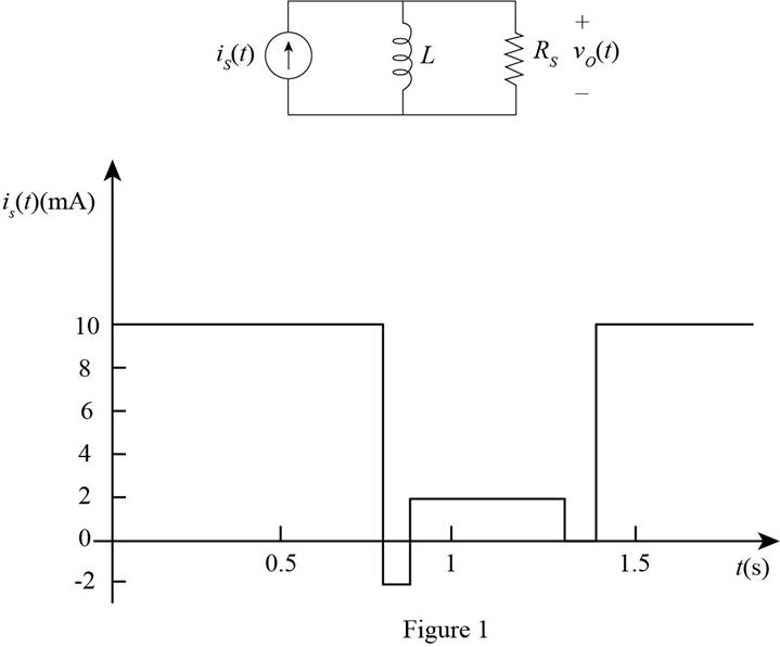
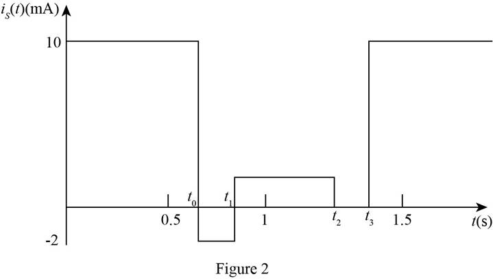
Mark the time interval on the source current waveform and redraw the circuit.
The required diagram is shown in Figure 2
The expression for the initial current through the inductor is given by,
The expression for the initial current through the inductor for time
For the circuit in DC steady state, inductor acts as the short circuit and the current through it is given by,
Substitute
The expression for the time constant of the circuit is given by,
Substitute
The expression for the complete solution for current is given by,
Substitute
The expression for the voltage across the inductor for the interval
Substitute
The expression for the current through the inductor for the time interval
For DC state the inductor is short circuited and the current through it is given by,
Substitute
The expression for the complete solution for current is given by,
Substitute
The expression for the voltage across the inductor for the interval
Substitute
The expression for the current through the inductor for the time interval
For DC state, the inductor is short circuited and the current through it is given by,
Substitute
The expression for the complete solution for current is given by,
Substitute
The expression for the voltage across the inductor for the interval
Substitute
The expression for the current through the inductor for the time interval
For DC state the inductor is short circuited and the current through it is given by,
Substitute
The expression for the complete solution for current is given by,
Substitute
The expression for the voltage across the inductor for the interval
Substitute
The expression for the current through the inducer for the interval
The current through the inductor for the steady state is given by,
Substitute
The expression for the complete solution for current is given by,
Substitute
The expression for the voltage across the inductor for the interval
Substitute
Thus, the expression for the voltage across the interval is given by,
From above expression, the waveform for the voltage across the circuit is shown below.
The required diagram is shown in Figure 3
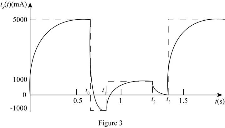
Conclusion:
Therefore, the waveform for the inductor voltage
Want to see more full solutions like this?
Chapter 5 Solutions
Principles and Applications of Electrical Engineering


- =7 Determine the current through the capacitor just before and just after the switch is closed in Figure P5.37. Assume steady-state conditions for t < 0. V = 12 V C = 150 µF R = 400 m2 R2 = 2.2 k2 t = 0 R1 + SI +)arrow_forwardGiven circuit below, use superposition to find voltage across the capacitor, vclt). Frequency is 100 Hz. 6kn 4kn reee zkn O SmA <45 Vc (t) DC a) Given circuit below and switch ciosed for long time, what is the value of Vc? 5mA 3 luk bị At0, switch is opened. Write a mathematical expression for Velt) after opening of the switch. Evaluate this voltage at te10 ms. Attach File Browse Local Fies rowie Conent Cotection 74°Farrow_forward4 If the switch in the circuit shown in Figure P5.64 is closed at t = 0 and Vs = 12 V C = 130 µF R = 2.3 k2 R, = 7 k2 L= 30 mH determine the current through the inductor and the voltage across the capacitor and across Rị after the circuit has returned to a steady state. t= 0 R1 Vs R2arrow_forward
- At 0-, no currrent flows through the capacitors because they are open, how did you combine the capacitors for the voltage divider since it is the capacitance value and not reactance, is it right? Can we just combine the capacitance value? Please explain. I did not understand..arrow_forwarda) The voltage across a 20uF capacitance is v. = 50 sin( at - 80) volts and Frequency equal to 100 Hz. Determine the current through the capacitor i and sketch its waveform. b) Define phasorarrow_forward1 Just before the switch is opened at t = 0, the current through the inductor is 1.70 mA in the direction shown in Figure P5.21. Did steady-state conditions exist just before the switch was opened? L= 0.9 mH Vs = 12 V R = 6 k2 R2 = 6 k2 R = 3 k2 t = 0 R2 R1 L R3{Va3 V83arrow_forward
- A circuit consisting of a resistor in series with a capacitor takes 100 watts at a power factor of 0.5 form a 100 V, 60 Hz supply. Find the current, resistance, the impedance and the capacitance.arrow_forwardThe time taken by the series RL circuit having an inductance of 0.6 H and resistance of 30 Ohms to reach a steady-state value.arrow_forward.A series RLC circuit contains a 4-kN resistor, an inductor with an inductive reactance (X,) of 3.5 kn, and a capacitor with a capacitive reactance (Xc) of 2.4 kN. A 120-Vac, 60-Hz power source is connected to the circuit. How much voltage is dropped across the inductor?arrow_forward
- A circuit has inductance of 2H. If the circuit current changes at the rate of 10 A/second, then self-induced e.m.f. is . .....arrow_forwardFor the network shown in Figure (Q5), Find: 1. The total equivalent inductance (Lequiv.). 2. If the current waveform shown in Figure (6) is applied to the (Leguiv). Determine an expression for the voltage across it. 6H 10 H 9H 4H SH 3 H 20 H 13H Lequiv. Figure (Q5) i (A) - (ms) 10 12 -5- Figure (6)arrow_forwardAn RC circuit has an emf of 5 V, a resistance of 10 ohms, a capacitance of 10 – 2 F, and initially a charge of 5 C on the capacitor. Determine the current flowing through the circuit. Ans.: I = - 99e – 10t/2arrow_forward
 Introductory Circuit Analysis (13th Edition)Electrical EngineeringISBN:9780133923605Author:Robert L. BoylestadPublisher:PEARSON
 Delmar's Standard Textbook Of ElectricityElectrical EngineeringISBN:9781337900348Author:Stephen L. HermanPublisher:Cengage Learning
 Programmable Logic ControllersElectrical EngineeringISBN:9780073373843Author:Frank D. PetruzellaPublisher:McGraw-Hill Education
 Fundamentals of Electric CircuitsElectrical EngineeringISBN:9780078028229Author:Charles K Alexander, Matthew SadikuPublisher:McGraw-Hill Education
 Electric Circuits. (11th Edition)Electrical EngineeringISBN:9780134746968Author:James W. Nilsson, Susan RiedelPublisher:PEARSON
 Engineering ElectromagneticsElectrical EngineeringISBN:9780078028151Author:Hayt, William H. (william Hart), Jr, BUCK, John A.Publisher:Mcgraw-hill Education,