
Concept explainers
Videos
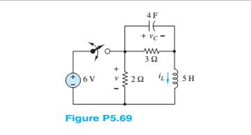
Assume the switch in the circuit in Figure P5.69has been closed for a very long lime. It is suddenly opened at
The inductor current
Answer to Problem 5.69HP
Explanation of Solution
Given:
The given circuit is shown below:
Calculation:
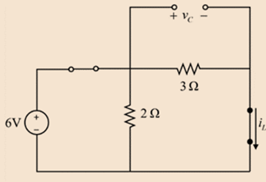
When switch is closed for long time means the circuit is in steady state condition. In this condition the capacitor is open circuited, and inductor is short circuited. Therefore, the modified circuit can be drawn as:
The current through the source just before the opening it at t = 0,
Applying the current division rule, the initial value of the current can be calculated as
The initial value of voltage across the capacitor will be
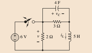
The switch is opened at t = 0, the circuit can be drawn as
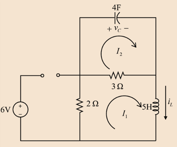
Applying KVL in the loop having current
Applying KVL in the loop having current
Differentiating with respect to t,
Put the value of
Assuming
The auxiliary equation can be written as
The roots can be calculated as
Therefore, the solution of the differential equation will be in the form
Current through the inductor is equal to the loop current,
Using the initial conditions,
At t = 0,
Substituting 0 for t,
Therefore,
Differentiating equation 2 with respect to t,
Substituting 0 for t,
Applying KVL in the loop with current
Substituting the values,
Substituting this in equation 4,
Substituting A and B in equation 2,
Substituting A and B in equation 3,
Put these values in equation 5,
Substitute
Substitute
Reclose the circuit. Now, the initial current in the inductor is represented as a voltage source of
Thus,
The initial voltage across the capacitor is represented as a voltage source of
The circuit can be drawn as
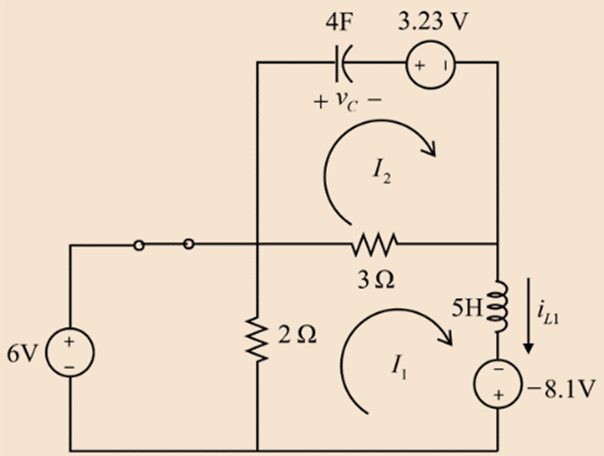
It can be observed that the voltage across the
Apply KVL in the loop with current
Apply KVL in the loop with current
Assuming
The auxiliary equation can be written as
The roots can be calculated as
Therefore, the solution of the differential equation will be in the form
Current through the inductor is equal to the loop current,
Using the initial conditions,
At t = 5,
Substituting 5 for t,
Differentiating equation 8 with respect to t,
Substituting 5 for t,
The voltage across the inductor at t = 5s will be
Substituting this in equation 10,
Substituting A and B in equation 8,
The complete solution can be calculated as
The 6V is always connected across the 2ohm resistor whenever the switch is closed. Therefore, the voltage across the 2ohm resistor will be
When the switch is opened, the current through the inductor flows through the 2ohm resistor. Thus, the voltage across the 2ohm resistor, when the switch is open will be
Substituting the value of
The voltage across the 2ohm resistor will be
Want to see more full solutions like this?
Chapter 5 Solutions
Principles and Applications of Electrical Engineering


- 2 Determine vc(t) for t > 0. The voltage across the capacitor in Figure P5.32 just before the switch is changed is given below. vc(0-) = -7 V I, = 17 mA C = 0.55 µF R = 7 k2 R2 = 3.3 k2 t= 0 R2 R1 CVct)arrow_forwardGiven circuit below, use superposition to find voltage across the capacitor, vclt). Frequency is 100 Hz. 6kn 4kn reee zkn O SmA <45 Vc (t) DC a) Given circuit below and switch ciosed for long time, what is the value of Vc? 5mA 3 luk bị At0, switch is opened. Write a mathematical expression for Velt) after opening of the switch. Evaluate this voltage at te10 ms. Attach File Browse Local Fies rowie Conent Cotection 74°Farrow_forwardA resistance and inductance are connected in series in a circuit containing an impressed voltage of 100V. The differential equation of E = Ri + Ldi/dt. Find the current when t=0.02s if R = 10 ohms and L = 2 henry.arrow_forward
- For the circuit shown in Figure Q2, determine the followi (a) The current in the inductors L1 and L2. (b) The voltage across the capacitors Cl and C2. (c) The total energy stored in the circuit. (d) The total power supplied by the source. 30V II RI -000-m 20mH 1052 50mH 2 R2 2002 300µF -000 30ml 91 300µF CI 600 μF R3 30Ω C3arrow_forwardAn LR circuit includes a resistor of resistance R, an inductor of inductance L and a battery of emf E = 10 V. At time t = 0 the current in the circuit is I = 0. At time t = 6.1 ms the current is I = 0.66 A. What are the values of L and R?arrow_forwardConsider the circuit shown in the figure. The capacitor is initially uncharged. Find the current across R2 after time t.arrow_forward
- What is the practical application of a circuit that you can tune such that it reaches some minimum resistance? Would there be an application to being able to tune where that minimum occurs, by changing the capacitance or inductance of the circuit?arrow_forwardDetermine v(t), the voltage across the 40 ohm resistor in the circuit in Figure P 5.3-7arrow_forwardWhen a switch is closed in a cirvuit containing a battery E,a resistance R and an inductance L,the current i build up at rate given by L di/dt +Ri=E.find "i" as a function "t"arrow_forward
- Q2/ For the network shown in figure (Q2), the switch has been open for a long time before closing at t-0. Determine an expression for the inductor (L-20mH) current İL() for 120. 300 tso 36V iL (2othH SoonF 15A lostarrow_forwardIn the figure you have a RL circuit with direct current. All resistors have resistance 30.0 , the inductors is 3.0 H. The battery provides a voltage of 840.0 V. At t=0 close the switch. At that instant, what are a) the current in the resistor R1? b) the current in the resistor R3? c) the voltage at the inductor L? +1 V m R1 switch M R2 A A V www R3arrow_forwardFor the circuit below with input voltage V1, a step function of magnitude 25 volts at time t-0, find the transient response voltage across the capacitor C1 and plot the results: (Provide your calculations and reasoning for your answer.) R1 555 250mH V1 = 0 V2 - 25 TD = 0 TR In V1 C1 TF in PW- 25 PER = 3.3uarrow_forward
 Introductory Circuit Analysis (13th Edition)Electrical EngineeringISBN:9780133923605Author:Robert L. BoylestadPublisher:PEARSON
 Delmar's Standard Textbook Of ElectricityElectrical EngineeringISBN:9781337900348Author:Stephen L. HermanPublisher:Cengage Learning
 Programmable Logic ControllersElectrical EngineeringISBN:9780073373843Author:Frank D. PetruzellaPublisher:McGraw-Hill Education
 Fundamentals of Electric CircuitsElectrical EngineeringISBN:9780078028229Author:Charles K Alexander, Matthew SadikuPublisher:McGraw-Hill Education
 Electric Circuits. (11th Edition)Electrical EngineeringISBN:9780134746968Author:James W. Nilsson, Susan RiedelPublisher:PEARSON
 Engineering ElectromagneticsElectrical EngineeringISBN:9780078028151Author:Hayt, William H. (william Hart), Jr, BUCK, John A.Publisher:Mcgraw-hill Education,