
Calculate the current response
Answer to Problem 57P
The current response
Explanation of Solution
Given data:
Refer to Figure 7.123 in the textbook.
The value of inductance
The value of inductance
Formula used:
Write the general expression to find the current response for the RL circuit.
Here,
Write the expression to calculate the time constant for the RL circuit.
Here,
L is the inductance of the inductor.
Write the general expression for the unit step function.
Calculation:
For
The given Figure 7.123 is redrawn as shown in Figure 1. At this condition, the inductor reaches steady state and acts like a short circuit to DC.

In Figure 1, apply Kirchhoff’s current law at node
Simplify the equation as follows,
Now find the initial inductor current
Substitute
Now find the initial inductor current
Substitute
For
Figure 2 shows the modified circuit diagram when the switch is kept in closed position.
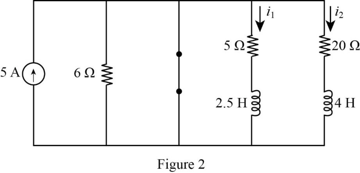
Consider the value of resistances
In Figure 2, the switch is closed so that the energies in the inductance
The current response
The time constant in equation (6) can be rewritten as like in equation (2) as follows.
Substitute
Substitute the units
Substitute
Apply the unit step function in equation (3) to equation (9).
The current response
The time constant in equation (10) can be rewritten as like in equation (2) as follows.
Substitute
Substitute the units
Substitute
Apply the unit step function in equation (3) to equation (13).
Convert the unit A to mA.
Conclusion:
Thus, the current response
Want to see more full solutions like this?
Chapter 7 Solutions
Fundamentals of Electric Circuits

- 176 7.29. Determine C/R for each system in Fig. 7-55. R (a) (b) (c) BLOCK DIAGRAM ALGEBRA AND TRANSFER FUNCTIONS OF SYSTEMS Supplementary Problems R R + S 5 G₁ H₁ G₂ G₁ H₁ G₂ G₁ H₁ Fig. 7-55 [CHAP. 7arrow_forwardExplain the duality theorem with example. Digital electronicsarrow_forwardElectrical Engineering Q7: Using the linear separability concept, obtain the response for OR function (rake bipolar inputs and bipolar targets). Table 7 163-164 / 489arrow_forward
- An independent voltage source is characterized by a terminal voltage which is completely independent of the current through it. Select one: True Falsearrow_forwardSeveral steps are required to find the thevenin voltage and resistance for a linear two-terminal circuit like that shown in Fig. (a). Identify whether each statement is true (Required) or False (not required) True or falsearrow_forwardExample 7.8: Apply nodal analysis to the network in Fig. 7.6(a). so www 40 2A R₁100 EMV W 40 -0 2A 100arrow_forward
- In the circuit of Fig. 7_1, what is Leq? -Lea] m 5777. 4H a b 8H 4H 10H Fig. 7_1 2H O Leg-7 H OL-17 H OL-SH O Log-15 H OL-20 H OL-32 H 4H m m 2Harrow_forward4. 7.38 PSPICEMULTISIM The switch in the circuit shown has been in position a for a long time before moving to position b at t=01. a) Find the numerical expressions for iL(t) and vo(t) for t≥0.2. b) Find the numerical values of vL(0+) and vo(0+)arrow_forwardfig. 7.80 for the Gufiguration of © find the currents I2, Is andl Is 5 find the Joltages Vy and us Ri R3 Ru R6 Rs R7 Ri 302 32arrow_forward
- In problem 12 in exercises 3.3 you were asked to show that currents i2(t) and i3(t) in the electrical network shown in figure 7.6.8 satisfy Ldi2/dt + L di3/dt+ R1i2=E(t) -R1di2/dt + R2di3/dt + 1/Ci3 =0arrow_forwardSource Transformation: Q7/ Use source transformation to find i, in the circuit shown in Fig. 7. 5 V 10 5A ЗАarrow_forwardFor the circuit shown in Fig.7. what will be the value of RL to get maximum power? Also,find this power.arrow_forward
 Introductory Circuit Analysis (13th Edition)Electrical EngineeringISBN:9780133923605Author:Robert L. BoylestadPublisher:PEARSON
 Delmar's Standard Textbook Of ElectricityElectrical EngineeringISBN:9781337900348Author:Stephen L. HermanPublisher:Cengage Learning
 Programmable Logic ControllersElectrical EngineeringISBN:9780073373843Author:Frank D. PetruzellaPublisher:McGraw-Hill Education
 Fundamentals of Electric CircuitsElectrical EngineeringISBN:9780078028229Author:Charles K Alexander, Matthew SadikuPublisher:McGraw-Hill Education
 Electric Circuits. (11th Edition)Electrical EngineeringISBN:9780134746968Author:James W. Nilsson, Susan RiedelPublisher:PEARSON
 Engineering ElectromagneticsElectrical EngineeringISBN:9780078028151Author:Hayt, William H. (william Hart), Jr, BUCK, John A.Publisher:Mcgraw-hill Education,