
Concept explainers
Videos
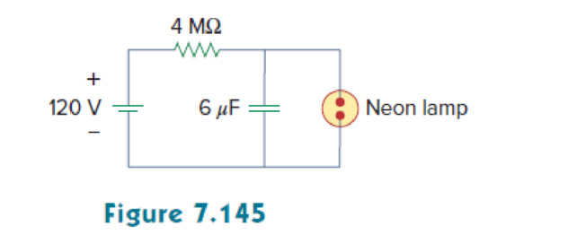
A simple relaxation oscillator circuit is shown in Fig. 7.145. The neon lamp fires when its voltage reaches 75 V and turns off when its voltage drops to 30 V. Its resistance is 120 Ω when on and infinitely high when off.
- (a) For how long is the lamp on each time the capacitor discharges?
- (b) What is the time interval between light flashes?
(a)
Calculate the discharge time of the capacitance when the lamp is on in the given circuit of Figure 7.145.
Answer to Problem 85P
The discharge time of the capacitance is
Explanation of Solution
Given data:
The neon lamp is on when its voltage reaches 75 V and turn off when its voltage drops to 30 V.
The resistance is
Refer to Figure 7.145 in the textbook.
The value of capacitance
Formula used:
Write the general expression to find the complete voltage response for an RC circuit.
Here,
Write the expression to find the time constant for an RC circuit.
Here,
C is the capacitance of the capacitor.
Calculation:
The neon lamp is on when it reaches 75 V. Therefore, the initial capacitor voltage
The neon lamp is off when it drops to 30 V. Therefore, the final capacitor voltage
When the neon lamp on and off, during that time a
Substitute
Substitute the units
Substitute
When the neon lamp is off, the voltage drops to 30 V. That is,
At
Substitute
Taking ln on both sides of the equation.
Rearrange the equation as follows,
Reduce the equation as follows,
Conclusion:
Thus, the discharge time of the capacitance is
(b)
Calculate the time interval between the light flashes.
Answer to Problem 85P
The time interval between the light flashes is
Explanation of Solution
Figure 1 shows the Thevenin resistance at the capacitance terminal.
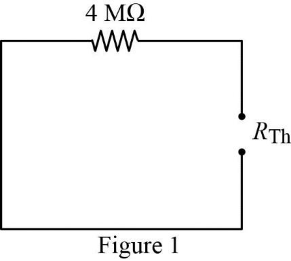
In Figure 1, the Thevenin resistance
Substitute
Substitute the units
At
At
Dividing the equation (6) by (7).
Consider the time interval is,
Substitute
Consider the neon lamp is on when its voltage
Substitute 75 V for
Taking ln on both sides of the equation.
Since, the time interval must be taken as positive value. Therefore,
Conclusion:
Thus, the time interval between the light flashes is
Want to see more full solutions like this?
Chapter 7 Solutions
Fundamentals of Electric Circuits


- 7- For the circuit below a) Find tbe time constant b) Sketch the waveforms for in, a when you close the switch AK 31m Harrow_forward1-A Pacemaker is a device that is implanted in the body and it helps to control the heartbeat by preventing the heart from beating too slowly. A pacemaker that is connected to a battery with a voltage of 9.0 V and has a capacitor with a capacitance of 110 µF is designed to deliver 5 pulses every 4 seconds. The pacemaker will deliver a pulse to the patients body every time its' capacitor is charged to 0.25 V. What resistance should the pacemaker have to achieve the desired pulse delivery (5 pulse every 4 second). 2-For the circuit below find the current in each resistor using the kirchoff method ww 3.9 1 12 V 1.20 9.8 Ω A ww 6.70 9.0 V Barrow_forward1. A cardiac defibrillator is used to shock a heart that is beating erratically. The capacitor is charged to 6.0kV in this device and stores 1800J of energy. What is the capacitance?arrow_forward
- 7-8 In a step-up converter, Va = 12 V, V, = 24 V,1, = 0.5 A, L = 150 µH, C = 470 µF, and f, 20 kHz. Calculate AV, (peak-peak). %3D %3D 7-9 In Problem 7-8, calculate the rms value of the ripple in the diode current (which also flows through the capacitor).arrow_forwardInductance is the property of an inductor that produces an opposition to any change in current. Select one: O True O Falsearrow_forwardThe magnitude of the voltage applied to the electrodes of a welding machine can be adjusted in the circuit below. In the range of minimum and maximum value that variable value resistor can take What is the time interval that the capacitor will charge from 0 to 8 V?arrow_forward
- 4) 7.125 N 4.752 ww ww 12 V 4 V 3F (a) Find the capacitor voltage and current for all time and sketch the waveforms in the same time axis.arrow_forwardMake a clamper circuit using 500 µF capacitor, silicon diode, and a 100 KΩ resistor connected to a 10 Vpeak sine wave. Draw the output waveform and indicate the amplitude and the time values supported by your solutions. Do these for both positive and negative clamper circuit. Show your circuits first before your solutions and waveforms.arrow_forwardWhat is the function of the holding capacitor in the circuit of Fig. 7?arrow_forward
- The given circuit has Vth=30V and Rth=30K Ohms. If the inductor will be short circuit and the switch will be closed, what will be the current i (in mA)?arrow_forwardEvery system response will have transient state before its steady-state due to O Energy Storage elements O bilateral elements O Energy consuming elements O linear elementsarrow_forwardA 2002 resistor, a 0.01 H inductor and a 100 µF capacitor are connected in series, A DC voltage of 100 V is suddenly applied to the circuit. Find the maximum current and the time at which it occurs.arrow_forward
 Delmar's Standard Textbook Of ElectricityElectrical EngineeringISBN:9781337900348Author:Stephen L. HermanPublisher:Cengage Learning