
Concept explainers
Videos
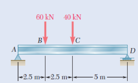
8.9 through 8.14 Each of the following problems refers to a rolled-steel shape selected in a problem of Chap. 5 to support a given loading at a minimal cost while satisfying the requirement σm ≤ σall. For the selected design, determine (a) the actual value of σm in the beam, (b) the maximum value of the principal stress σmax at the junction of a flange and the web.
8.14 Loading of Prob. 5.78 and selected S460 × 81.4 shape.
Fig. P5.78
(a)
The actual value of
Answer to Problem 14P
The actual value of
Explanation of Solution
Given information:
Refer to problem 5.78 in chapter 5 in the textbook.
The allowable normal stress of the beam is
Calculation:
Design of beam:
Show the free-body diagram of the beam as in Figure 1.
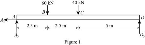
Determine the vertical reaction at point D by taking moment at point A.
Determine the vertical reaction at point A by resolving the vertical component of forces.
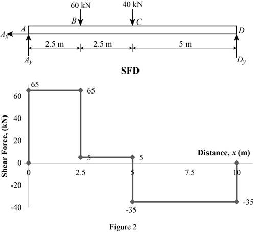
Shear force:
Show the calculation of shear force as follows;
Show the calculated shear force values as in Table 1.
| Location (x) m | Shear force (V) kN |
| A | 65 |
| B (Left) | 65 |
| B (Right) | 5 |
| C (Left) | 5 |
| C (Right) | –35 |
| D | –35 |
Plot the shear force diagram as in Figure 2.
Bending moment:
Show the calculation of the bending moment as follows;
Show the calculated bending moment values as in Table 2.
| Location (x) m | Bending moment (M) kN-m |
| A | 0 |
| B | 162.5 |
| C | 175 |
| D | 0 |
Plot the bending moment diagram as in Figure 3.
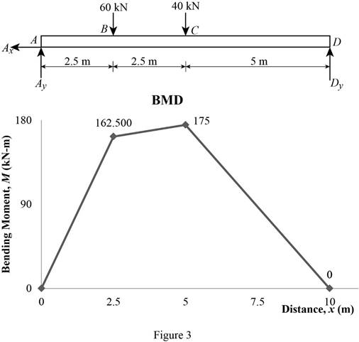
Refer to the Figure 3;
The maximum bending moment in the beam is
Write the section a property for a
| Dimension | Unit( |
| d | 457 |
| 152 | |
| 17.6 | |
Here, d is depth of the section,
Find the value of C using the relation:
Substitute
Find the maximum value of normal stress
Here,
Substitute
Thus, the actual value of
(b)
The maximum value of principal stress
Answer to Problem 14P
The maximum value of principal stress
Explanation of Solution
Calculation:
Find the value
Here, c is the centroid and
Substitute
Find the area of flange
Here,
Substitute
Find the centroid of flange
Substitute
Find the first moment about neutral axis
Here,
Substitute
At section C,
Find the value of
Here, actual value of normal stress
Substitute
Find the shear stress at
Modify Equation (8).
Substitute
Find the maximum shearing stress (R) using the relation:
Here,
Substitute
Determine the maximum value of the principle stress using the relation:
Here, R is the maximum shearing stress and
Substitute
At section B,
Find the maximum value of normal stress
Here,
Substitute
Find the value of
Substitute
Find the shear stress at b
Substitute
Refer to figure 3.
Substitute
Find the maximum shearing stress (R) using the relation:
Here,
Substitute
Determine the maximum value of the principle stress using the relation:
Here, R is the maximum shearing stress and
Substitute
Based on results,
Select the maximum value of principal stress
Thus, the maximum value of principal stress
Want to see more full solutions like this?
Chapter 8 Solutions
Mechanics of Materials, 7th Edition
Additional Engineering Textbook Solutions
Statics and Mechanics of Materials (5th Edition)
Machine Tool Practices (10th Edition)
Vector Mechanics For Engineers
Engineering Mechanics: Statics & Dynamics (14th Edition)
Heat and Mass Transfer: Fundamentals and Applications
Introduction to Heat Transfer


- Problem 1): A circular pipe girder is constructed from 80mm external diameter and 60 mm internal diameter. Three such girders are mounted vertically one at equal angles of a circular horizontal platform which the girders support. The platform is 5 m above ground level and weighs (0.1*B) KN. The platform supports an additional central load of (0.2*B) KN. The weight of the girders may not be neglected. The density of the material from which the girders are constructed is (290*B) kg/m3. Assuming that each girder supports an equal share of the load, determine the compressive stresses set up in the material of each girder:1- At the lower point of the girder.2- At the middle point of the girder.3- At the upper point of the girder. Discuss the above values when the weights of the girders are neglected.Note: B = 39 Problem 2): A 20 mm diameter steel rod passes concentrically through a bronze tube (200+Q) mm long, 50 mm external diameter, and 40 mm internal diameter. The ends of the steel rod…arrow_forwardA 20 mm diameter steel rod passes concentrically through a bronze tube (200+SN) mm long, 50 mm external diameter and 40 mm internal diameter. The ends of the steel rod are threaded and provided with nuts and washers which are adjusted initially so that there is no end play at 25°C.. 1. Assuming that there is no change in the thickness of the washers, if the stress produced in the steel is (200+SN) MN/m2 when one of the nuts is tightened, the pitch of the thread being 1 mm. Find the number of turns for the nut and stress in bronze tube.2. If the temperature of the steel and bronze is then raised to 4O°C find the changes that will occur in the stresses in both materials. The coefficient of linear expansion per C is 10 x10-6 for steel and 17 x10-6 for bronze. E for steel = 210 GN/m2. E %3D for bronze = 100 GN/m2.. Note: SN = %3D Student number Student Number =32arrow_forwardProblem Steel block with triaxial loading as shown, y 2" 3" For Steel, E = 29 x 106 Psi y = 0.3 Loads: (Original Loading – Load are Uniformly Distributed Along Their Axis) F; = 48 Kips (T) Fy 60 Kips (C) F2 54 Kips (T) Required: Determine the magnitude F,'of the single uniformly distributed load in the x- direction that would produce the same deformation in the y-direction as the original loading. F + F2 Fyarrow_forward
- |This problem is just like the example problem, but dimension changed so centroid and moment of inertia change, AND the applied load is up and not down. - 3". - 3"-| A vertical force P of magnitude 20 kips is applied at point C located on the axis of symmetry of the cross section of a short column. Knowing that y = 11" determine at the top of column B 2" 6" the stress @ pt A @ pt b @ pt C @ the N.A. A 4" 2" Y' 2" 1/2"arrow_forwardA draw bar between a tractor and a trailer is made from a length of steel with a rectangular cross-section 100 mm by 12 mm. The load is transmitted to the bar via a pin through a 25 mm diameter hole at each end as shown in Fig. 4c. for 100 Fig. 4c If the load P in the bar is 100 kN, determine the following: The stress at the section X-X, shown in Fig. 4c. i (6 marks) ii The stress at the section Y-Y, shown in Fig. 4c. (5 marks)arrow_forwardEach of the three rolled-steel beams shown (numbered 1, 2, and 3) is to carry a 64-kip load uniformly distributed over the beam. Each of these beams has a 12-ft span and is to be supported by the two 24-ft rolled-steel girders AC and BD. The allowable normal stress for the steel used is 22.5 ksi. Determine the section modulus for each girder and select the most economical W shape for the two girders using the table given below. (Round the final answer to one decimal place.)arrow_forward
- а) An annular washer distributes the load P applied to a steel rod to a timber support. The rod's diameter is 22 mm, and the washer's inner diameter is 25 mm, which is larger than the hole's permissible outer diameter. Knowing that the axial normal stress in the steel rod is 35 MPa and the average bearing stress between the washer and the timber must not exceed 5 MPa, examine the smallest allowed outer diameter, d, of the washer. - 22 mm Figure 4arrow_forward2. (a) A steel cylinder of 60 mm inner radius and 80 mm outer radius is subjected to an internal pressure of 30 MNm ². Determine the resulting hoop stress values at the inner and outer surfaces and graphically represent (sketch) the general form of hoop stress variation through the thickness of the cylinder wall. (b) (c) The cylinder in (a) is to be used as a shrink-fitted sleeve to strengthen a hydraulic cylinder manufactured of the same steel. The cylinder bore radius is 40 mm. When the hydraulic cylinder is not subjected to internal pressure, the interference pressure generated due to the shrink fit alone is 30 MNm2. Note: This is the same value of pressure as in the problem analysed in part (a). Determine the resulting hoop stress values at the inner and outer walls of the inner cylinder. Graphically represent the general form of hoop stress variation through the wall thickness in the combination indicating the key values as calculated in parts (a) and (b). (d) If the Young's…arrow_forward1. A cantilever of square cross section as shown was made of mild carbon steel SAE 1020, as rolled, and was designed to support a static load W = 15 lb. After the beam was installed, it was discovered that the weight W was not static but vibrated, so that actually the beam was subjected to a repeated load. Measurement showed that the weight rose and fell a distance h equal to 0.05 inch. Shortly thereafter the beam fractured at the fillet which had a machined radius of 1/32 in. (a) Make calculations to show and state your conclusion whether or not the beam should have been expected to fail. (b) for the same data, design a new cantilever with the same dimensions except with a fillet radius r= 1/8 in. Determine whether a carbon steel would be necessary, and if so, its SAE or AISI no. 1/2" 3/4". 6"arrow_forward
- Problem !. , The steel tie bar shown is to be designed to carry a tension force of magnitude P = 130KN when bolted between double brackets at A and B. The bar will be fabricated from 25-mm-thick plate stock. For the grade of steel to be used, the maximum allowable stresses are: o = 170 MPa, t = 110 MPa, op = 370 MPa. Design the tie bar by determining the required values of: a. the diameter d of the bolt, b. the dimension b at each end of the bar, c. the dimensionh of the bar.arrow_forwardPROBLEM NO. 2 A flanged bolt coupling connects two shafts. The bolt circle diameter is 250 mm in which there are 12 bolts. The allowable shear stress is 50 MPa in the shafts and 23 MPa in the bolts. One shaft is hollow with outside diameter of 100 mm, while the other one is solid of diameter 50 mm. Determine the ratio of the outside and inside diameter of the hollow shaft and the bolt diameter so that both shafts and the flanged bolt coupling are having the same strength in torsion.arrow_forwardB The steel tie bar shown is to be designed to carry a tension force of magnitude P = 120 kN when bolted between double brackets at A and B. The bar will be fabricated from 20-mm-thick plate stock. For the grade of steel to be used, the maximum allowable stresses are: o = 175 MPa, ↑ = 100 MPa, o, 350 MPa. Design the tie bar by determining the required values of (a) the diameter d of the bolt, (b) the dimension b at each end of the bar, (c) the dimension h of the bar.arrow_forward
 Elements Of ElectromagneticsMechanical EngineeringISBN:9780190698614Author:Sadiku, Matthew N. O.Publisher:Oxford University Press
 Mechanics of Materials (10th Edition)Mechanical EngineeringISBN:9780134319650Author:Russell C. HibbelerPublisher:PEARSON
 Thermodynamics: An Engineering ApproachMechanical EngineeringISBN:9781259822674Author:Yunus A. Cengel Dr., Michael A. BolesPublisher:McGraw-Hill Education
 Control Systems EngineeringMechanical EngineeringISBN:9781118170519Author:Norman S. NisePublisher:WILEY
 Mechanics of Materials (MindTap Course List)Mechanical EngineeringISBN:9781337093347Author:Barry J. Goodno, James M. GerePublisher:Cengage Learning
 Engineering Mechanics: StaticsMechanical EngineeringISBN:9781118807330Author:James L. Meriam, L. G. Kraige, J. N. BoltonPublisher:WILEY