
Concept explainers
Videos
Three forces are applied to the bar shown. Determine the normal and shearing stresses at (a) point a, (b) point b, (c) point c.
Fig. P8.47
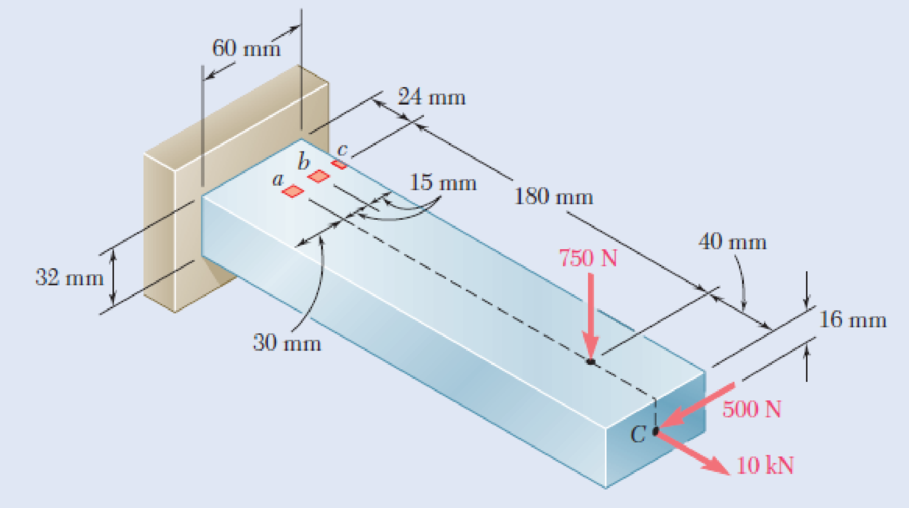
8.48 Solve Prob. 8.47, assuming that the 750-N force is directed vertically upward.
(a)
The normal and shearing stress at point a.
Answer to Problem 48P
The normal stress at point a is
The shear stress at point a is
Explanation of Solution
Given information:
Assume
Calculation:
At point A:
Find the area of cross section
Here, b is the width of the bar and h is the height of the bar.
Substitute
Find the moment of inertia
Substitute
Find the moment of inertia
Substitute
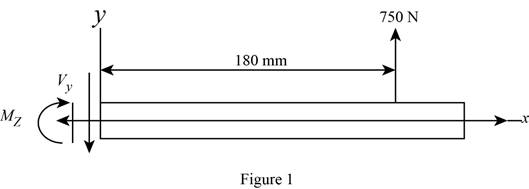
Sketch the side view of bar as shown in Figure 1.
At the section containing point a, b, and c.
Refer to Figure 1.
Find the moment about z axis as follows:
Sketch the side view of bar as shown in Figure 2.
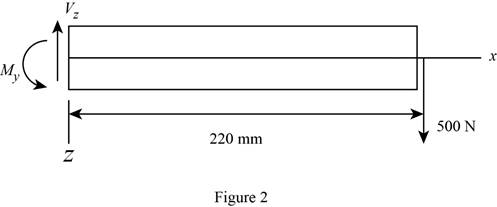
Find the moment about y axis as follows:
Find the normal stress
Here, P is the centric force, A is the area of rectangular cross section,
Substitute
Thus, the normal stress at point a is
Sketch the cross section at point a as shown in figure 3.
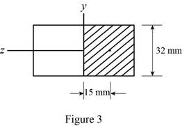
Determine the first moment area (Q) as follows:
Here,
Refer to Figure 2.
Substitute
Find the shear stress
Here,
Substitute
Thus, the shear stress at point a is
(b)
The normal and shearing stresses at point b.
Answer to Problem 48P
The normal stress at point b is
The shear stress at point b is
Explanation of Solution
Calculation:
At point b:
Find the normal stress
Substitute
Thus, the normal stress at point b is
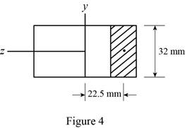
Sketch the cross section at point b as shown in figure 4.
Determine the first moment area (Q) as follows:
Here,
Refer to Figure 2.
Substitute
Find the shear stress
Here,
Substitute
Thus, the shear stress at point b is
(c)
The normal and shearing stresses at point c.
Answer to Problem 48P
The normal stress at point c is
The shear stress at point c is
Explanation of Solution
Calculation:
Find the normal stress
Substitute
Thus, the normal stress at point c is
Find the shear stress
The point c is edge on the cross section. Since Q is zero.
Substitute
Thus, the shear stress at point c is
Want to see more full solutions like this?
Chapter 8 Solutions
Mechanics of Materials, 7th Edition


- A steel pipe of 300-mm outer diameter is fabricated from an 8-mm-thick plate by welding along a helix that forms an angle of 20° with a plane perpendicular to the axis of the pipe. Knowing that a 250-kN axial force P and a 12-kN-m torque T. each directed as shown, are applied to the pipe, determine the normal and in-plane shearing stresses in directions, respectively, normal and tangential to the weld. T The normal stress is - The shear stress is- Weld 20⁰ 8 mm MPa MPa.arrow_forwardProblem 2. Three loads are applied to the short rectangular post shown In Fig. 2(a). The cross- sectional dimensions of the post are shown in Fig. 2(b). Determine: Me (a) The normal and shear stresses and points H and K; (b) The principal stresses and maximum in-plane shear stress at point H, and show the orientation of theses stresses in an appropriate sketch. No. M2 y 50 mm 210 kN %3D 120 mm (Naー 75 mm K 65 kN 30 mm 95 kN 160 mm 150 mm 30 mm Y-axis is the w to the sectin paimt Hond E امقره Fig. 2(b) 文 Section Proputics A= 120 X160=19200 mm Lx=160 - 40960000 mm-4094r L= 160x128 5KNス50 m-) %3D %3D = 23040000mm'= 23; 40Xlʻmm7 Int Faicesarrow_forwardPROBLEM 7.26 0.2 m The axle of an automobile is acted upon by the forces and couple shown. Knowing that the diameter of the solid axle is 32 mm, determine (a) the principal planes and principal stresses at point H located on top of the axle, (b) the maximum shearing stress at the same point. 3 kN 350 N- m 3 kN Omax = 18.67 MPa = -158,5 MPa O minarrow_forward
- Problem 8.12 A bar of rectangular cross-section, with a width of 60 mm and a thickness of 40 mm, is bent in the shape of a horse shoe having a mean radius of 70 mm. Two equal and opposite forces of 10 kN each are applied at a distance of 12 cm from the centre line of the middle section so that they tend to straighten the rod. Find the maximum ten- sile and compressive stresses and construct a diagram showing the vari- ation of the normal stresses over the central section.arrow_forward60 MPa PROBLEM 7.3 45 MPa For the given state of stress, determine the normal and shearing stresses exerted on the oblique face of the shaded triangular element shown. Use a method of 120 MPA analysis based on the equilibrium of that element, as was done in the 70° derivations of Sec. 7.2. O=14.19 MPa T = 15.19 MPaarrow_forwardProb.4: [2.37] The 1.5 m concrete post is reinforced with six steel bars, each with 28 mm diameter. Knowing the E, = 200 GPa and Ec = 200 GPa, determine the normal stresses in the steel and concrete when a 1550 kN axial centric force P is applied to the post. 450 mm 1.5 marrow_forward
- Que 5.6. A crane hook trapezoidal horizontal cross-section is 50 mm wide inside and 30 mm wide outside. Thickness of the section is 60 mm. The crane hook carries a vertical load of 20 kN whose line of action is 50 mm from the inside edge of the section. The center of curvature is 60 mm from the inside edge. Determine the maximum tensile and compressive stresses in the section.arrow_forward19. knowing that a force P of magnitude 75 N is applied to the pedestal shown, determine (a) the diameter of the pin at C for which the average shearing stress in the pin is 40 MPa, (b) the corresponding bearing stress in the pedestal at C, (c) the corresponding bearing stress in each support bracket at C. 75 mm 9 mm - 300 mm- B 125 mm D 5 mmarrow_forwardTwo forces P can be applied separately or at the same time to a plate that is welded to a solid circular bar of radius r. Determine the largest compressive stress in the circular bar (a) when both forces are applied, (b) when only one of the forces is applied.arrow_forward
- In the hanger shown the upper portion of link ABC is 9-mm thick and the lower portions are each 6-mm thick. Epoxy resin is used to bond the upper and lower portions together at B. The pin at A is of 9-mm diameter while a 6-mm-diameter pin is used at C. Determine (a) the shearing stress in pin A. (b) the shearing stress in pin C, (c) the largest normal stress in link ABC, (d) the average shearing stress on the bonded surfaces at B, (e) the bearing stress in the link at C. 30 mm 150 mm 40 mm 170 mm 240 mm 2400 N 120 marrow_forwardQuestion 3. A 4 by 4-in. wood-post BC is connected to a 1-in. diameter steel eye-bar AB to form a hoist. A load of w = 7000 Ibs is applied at point B on the hoist. (a)Determine the axial stresses in members AB and BC. (b) Determine the cross shearing stress in the 1-in. diameter bolt at point A. STEEL V -7000 lb WOOD FIG. I Aarrow_forward! 4 Required information Two horizontal 5.5-kip forces (P) are applied to pin B of the assembly shown. A 0.8-in. diameter pin is used at each connection. Part 2 of 2 0.5 in. 1.8 in. P 0.5 in. 60° 1.8 in. Determine the maximum value of the normal average stress at the midpoint of link BC. The maximum value of the normal average stress at the midpoint of link BC is ksi.arrow_forward
 Elements Of ElectromagneticsMechanical EngineeringISBN:9780190698614Author:Sadiku, Matthew N. O.Publisher:Oxford University Press
 Mechanics of Materials (10th Edition)Mechanical EngineeringISBN:9780134319650Author:Russell C. HibbelerPublisher:PEARSON
 Thermodynamics: An Engineering ApproachMechanical EngineeringISBN:9781259822674Author:Yunus A. Cengel Dr., Michael A. BolesPublisher:McGraw-Hill Education
 Control Systems EngineeringMechanical EngineeringISBN:9781118170519Author:Norman S. NisePublisher:WILEY
 Mechanics of Materials (MindTap Course List)Mechanical EngineeringISBN:9781337093347Author:Barry J. Goodno, James M. GerePublisher:Cengage Learning
 Engineering Mechanics: StaticsMechanical EngineeringISBN:9781118807330Author:James L. Meriam, L. G. Kraige, J. N. BoltonPublisher:WILEY