
Concept explainers
Videos
(a) Assuming the passive sign convention, obtain an expression for the voltage across the 1 Ω resistor in the circuit of Fig. 9.41 which is valid for all t > 0. (b) Determine the settling time of the resistor voltage.
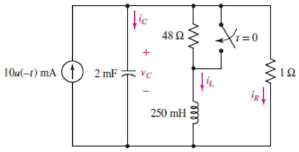
■ FIGURE 9.41
(a)
Obtain an expression for voltage across
Answer to Problem 15E
The expression for voltage across
Explanation of Solution
Formula used:
The expression for the exponential damping coefficient or the neper frequency is as follows:
Here,
The expression for the resonating frequency is as follows:
Here,
The expression for the two solutions of the characteristic equation of a parallel
Here,
The expression for the natural response of the parallel
Here,
Calculation:
The redrawn circuit diagram is given in Figure 1 for
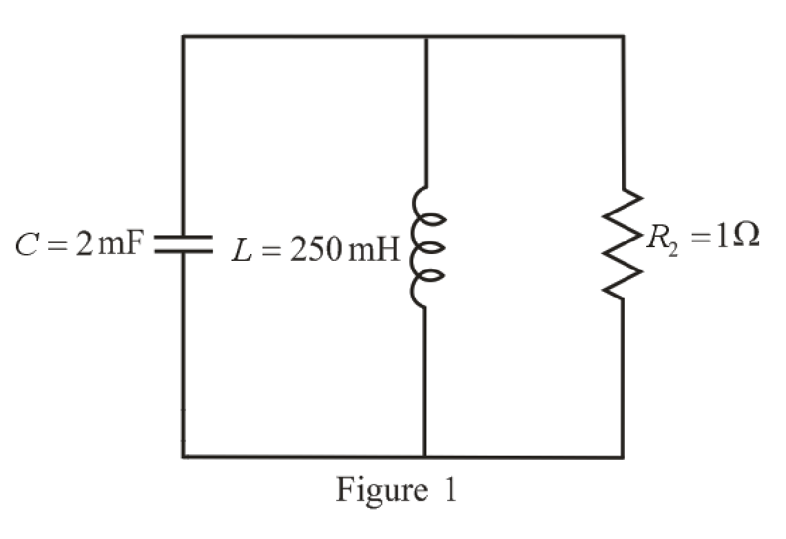
Refer to the redrawn Figure 1:
Substitute
Substitute
As value of neper frequency
Substitute
Substitute
The unit-step forcing function as a function of time which is zero for all values of its argument less than zero and which is unity for all positive values of its argument.
Here,
So, at
The capacitor and the inductor are connected in the circuit for long time.
So, the capacitor behaves as open circuit and the inductor behaves as short circuit.
The redrawn circuit diagram is given in Figure 2 for
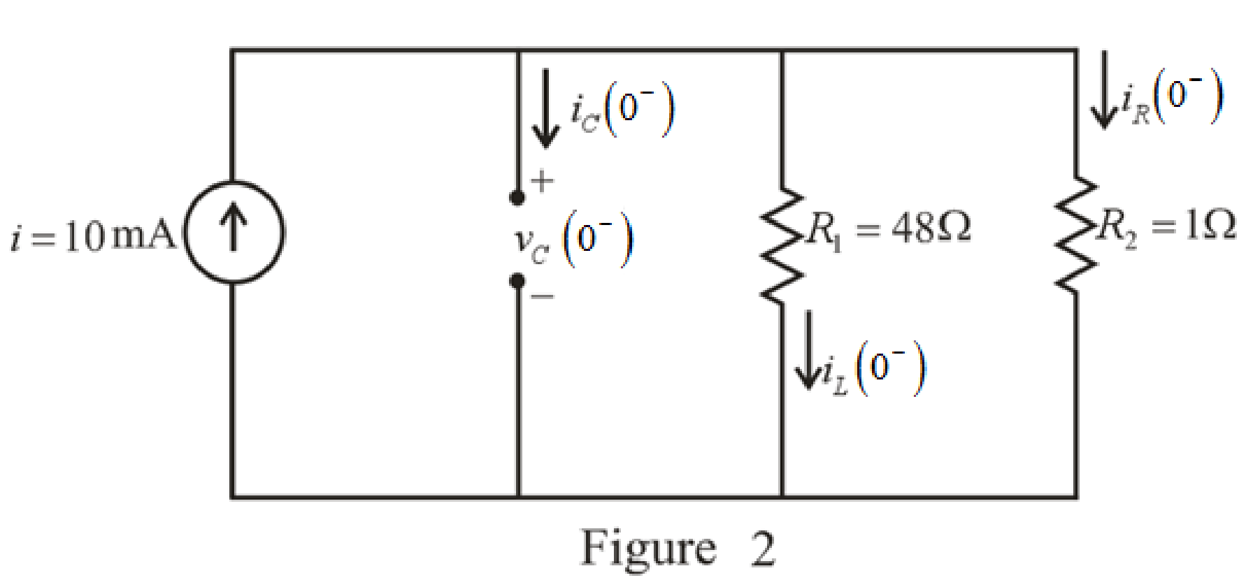
Refer to the redrawn Figure 2:
The expression for the current flowing in the
Here,
Substitute
The expression for the voltage across the
Here,
Substitute
The switch closes at
The capacitor does not allow sudden change in the voltage and the capacitor does not allow sudden change in the current.
So,
As parallel branches have same voltage across them, so, voltage across resistor
Therefore,
The redrawn circuit diagram is given in Figure 3 for
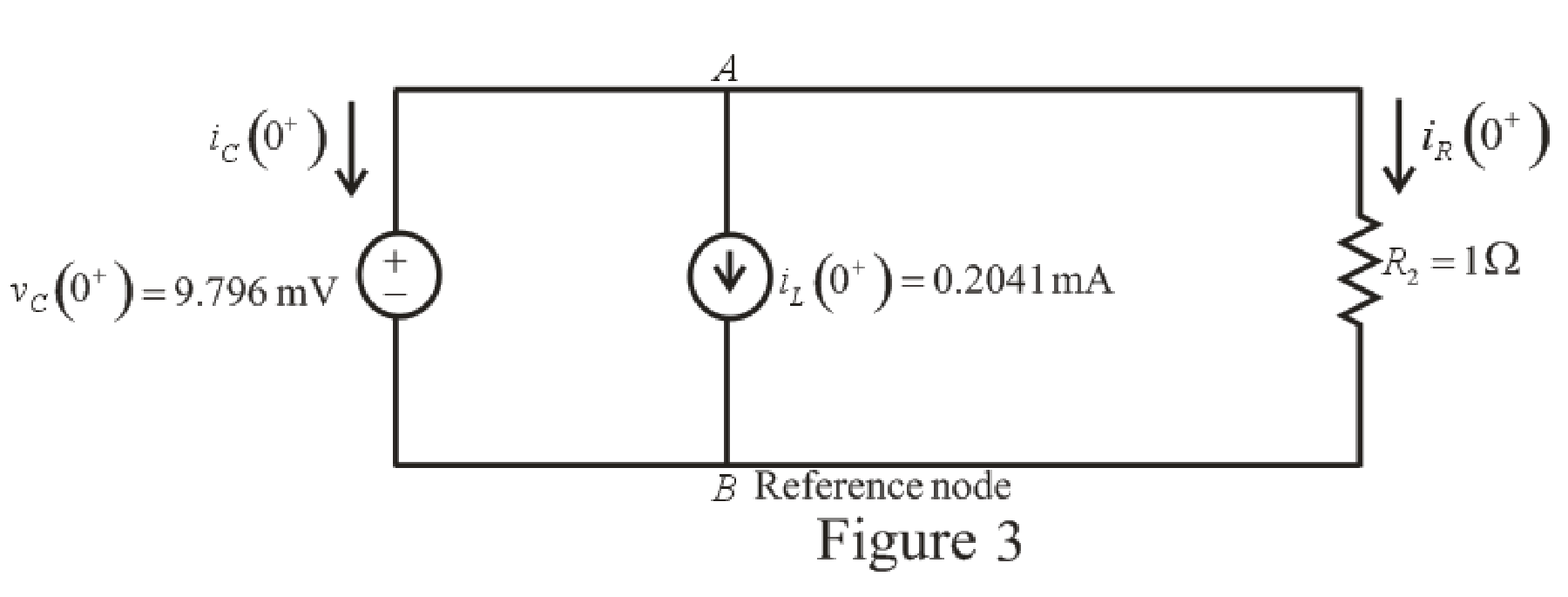
Refer to the redrawn Figure 3:
The expression for the current flowing in the resistor
Here,
Substitute
Apply KCL at node
Here,
Substitute
Rearrange for
Substitute
Substitute
The voltage across the resistor
Substitute
Rearrange for
The expression for the current flowing through the
Substitute
Rearrange for
Substitute
The current flowing through the
Substitute
Rearrange for
Substitute
Rearrange for
Substitute
Substitute
Conclusion:
Thus, expression for voltage across
(b)
Find settling time of the resistor voltage.
Answer to Problem 15E
The settling time is
Explanation of Solution
Calculation:
Function for voltage across resistor
The maximum value of voltage
Substitute
So, the maximum value of voltage
Settling time is the time at which the value of the voltage
The expression for the voltage
Here,
Substitute
Substitute
Since the component
So, the new equation is:
Rearrange equation (20).
Take natural logarithm both sides.
Conclusion:
Thus, the settling time is
Want to see more full solutions like this?
Chapter 9 Solutions
Loose Leaf for Engineering Circuit Analysis Format: Loose-leaf


- A suspension string has 3 units. Each unit can withstand a maximum peak voltage of 11kV. The capacitance of each joint and metal work is 20% of the capacitance od each disc. Find (i) maximum line voltage for which the string can be used. (ii) string efficiencyarrow_forward1.2Solve the total resistance, total current, individual currents, and individual voltages of the following dc circuits. EngineeringElectrical EngineeringCircuit Theoryarrow_forwardThe natural response is the behavior of a circuit for a long time when an external excitation is applied. True Falsearrow_forward
- -5.0000 -1.0000 + 1.0000i -1.0000 - 1.0000i The roots of the system characteristic equation are: * a) The system is stable. b) The system is unstable. c) The system is marginally (critically) stable.arrow_forward2. Determine if following systems are stable, asymptotically stable or unstable using Lyapunov's Method. (1) X₁ (3) X₁ = sinx2, x₂ = 0 = sinx2, X₂ = -x1-x₂ (2) *₁ (4) X₁ = = sinx₂, x₂ = -X₁ sinx2, X2 = -x₁ + x₂arrow_forwardCapacitance= 9uF Determine the time constant of the circuit for the capacities. For the capacity value, calculate the estimated time to come to the final state. Plot capacitor current and voltage graphs and show if it works in harmony with the time constant you calculated. NOTE: if you want you can use falstad online circuit simulator.arrow_forward
- b) Find the Node voltage at point “a". Give the answer as a function of time Va(t)= ? Note: Be careful about the terminal signs. (10p) O 20cos ( 100t) V A 10 sin (100tt!s@) V -5tj2 V O - 10 (36° Varrow_forwardSolve the damping ratio of the given system, Figure 10, if D=1, %OS = 30% and Ts = 3 sec. The input is a unit step. %3D T(t) oll FIGURE 10 O No correct answer. My solution is attached at the last part. O 0.6784 O 0.3579 O 0.5432arrow_forward%AO O ".ll Asiacell|ASIACELL Electrical Engineering Que.. www.bartleby.com m m Q&A Sign in Engineering / Electrical Engineeri... / Q&A Libr... I- Electrical Engineering Question Standard Chartered S The switch in the circuit shown has been closed for a long time. At t 0, the switch is opened. Find the final value of Vc? 100 20 2 1=0 I mA ( 2 mF 30 N 15 0 ful Expert Answer This question hasn't been answered yet. •••arrow_forward
- Please it's all the same problem, help me. Thank youarrow_forwardWrite the differential equation for t > 0 for iC in the given figure. Assume VS = 9 V, RS = 4 kohm, R1 = 11 kohm, and R2 = R3 = 20 kohm.arrow_forwarda) What is the coupling constant between the two coils?b) Using the dot notation, determine if the induced voltages are additive or subtractive?c) Write the expressions for V1(t) and V2(t).d) Using KVL, determine the differential equation needed to solve for I2(t).e) Solve the differential equation in part d to get I2(t). Assume no energy stored in inductors at t=0.f) Use I1(t) and I2(t) to determine V1(t) and V2(t).arrow_forward
 Introductory Circuit Analysis (13th Edition)Electrical EngineeringISBN:9780133923605Author:Robert L. BoylestadPublisher:PEARSON
 Delmar's Standard Textbook Of ElectricityElectrical EngineeringISBN:9781337900348Author:Stephen L. HermanPublisher:Cengage Learning
 Programmable Logic ControllersElectrical EngineeringISBN:9780073373843Author:Frank D. PetruzellaPublisher:McGraw-Hill Education
 Fundamentals of Electric CircuitsElectrical EngineeringISBN:9780078028229Author:Charles K Alexander, Matthew SadikuPublisher:McGraw-Hill Education
 Electric Circuits. (11th Edition)Electrical EngineeringISBN:9780134746968Author:James W. Nilsson, Susan RiedelPublisher:PEARSON
 Engineering ElectromagneticsElectrical EngineeringISBN:9780078028151Author:Hayt, William H. (william Hart), Jr, BUCK, John A.Publisher:Mcgraw-hill Education,