
Videos
Determine expressions for vC(t) and iL(t) in Fig. 9.59 for the time windows (a) 0 < t <2 μs and (b) t > 2 μs.
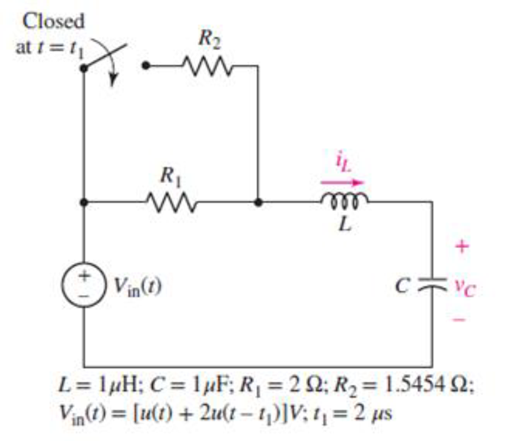
FIGURE 9.59
(a)
Determine expressions for
Answer to Problem 62E
The expressions for
Explanation of Solution
Given Data:
The range of the time is
Formula used:
The expression for the exponential damping coefficient or the neper frequency for series
Here,
The expression for the resonant frequency for series
Here,
The expression for complete natural response for source free series
Here,
The expression for the critically damped natural response of the series
Here,
Calculation:
The unit-step forcing function as a function of time which is zero for all values of its argument less than zero and which is unity for all positive values of its argument.
Here,
So, at
Since the series
The capacitor does not allow sudden change in the voltage and the inductor does not allow sudden change in the current.
So,
And,
Therefore, the voltage across the capacitor at
At
The redrawn circuit diagram is given in Figure 1 at
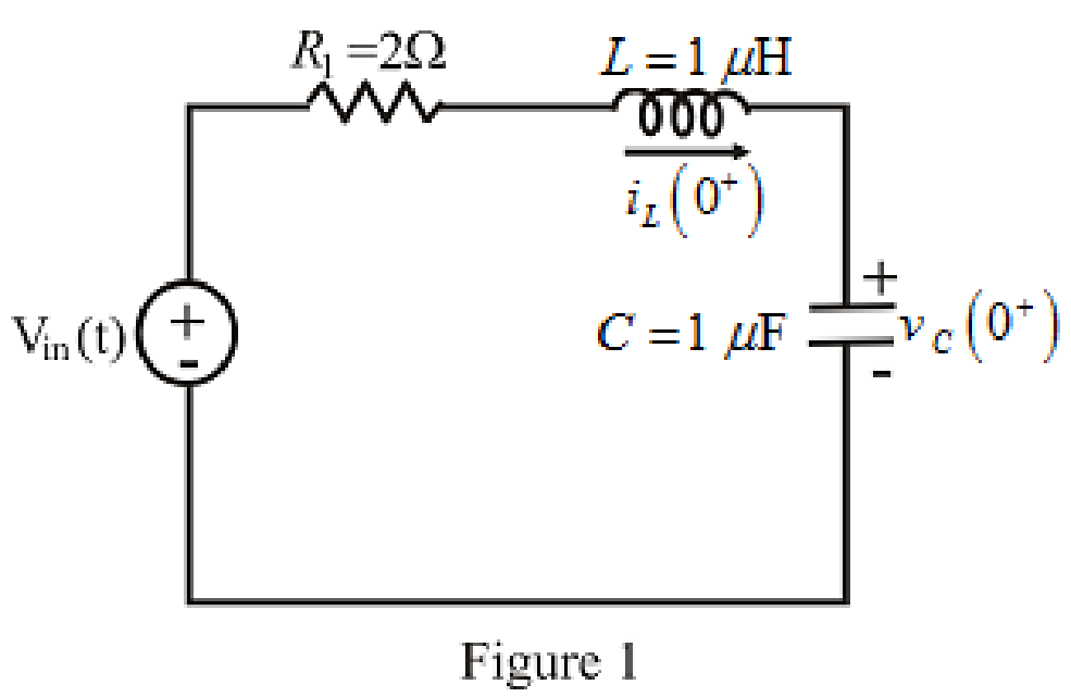
Refer to the redrawn Figure 1:
Substitute
Substitute
Here, the resonant frequency is equal to the exponential damping coefficient.
Therefore, the response of the circuit is critically damped.
At
Therefore, the value of forced response
Substitute
Substitute
The voltage across the capacitor at
Substitute
Rearrange for
The expression for the current flowing through
So, the current flowing through
The expression for the current flowing through the
Substitute
Rearrange for
Substitute
The current flowing through
Substitute
Substitute
Rearrange for
Substitute
The expression for the current flowing through the
Substitute
Substitute
Conclusion:
Thus, the expressions for
(b)
Determine expressions for
Answer to Problem 62E
The expressions for
Explanation of Solution
Formula used:
The expression for the damped natural frequency in series
Here,
The expression for natural response for series
Here,
Calculation:
The redrawn circuit diagram is given in Figure 2 at
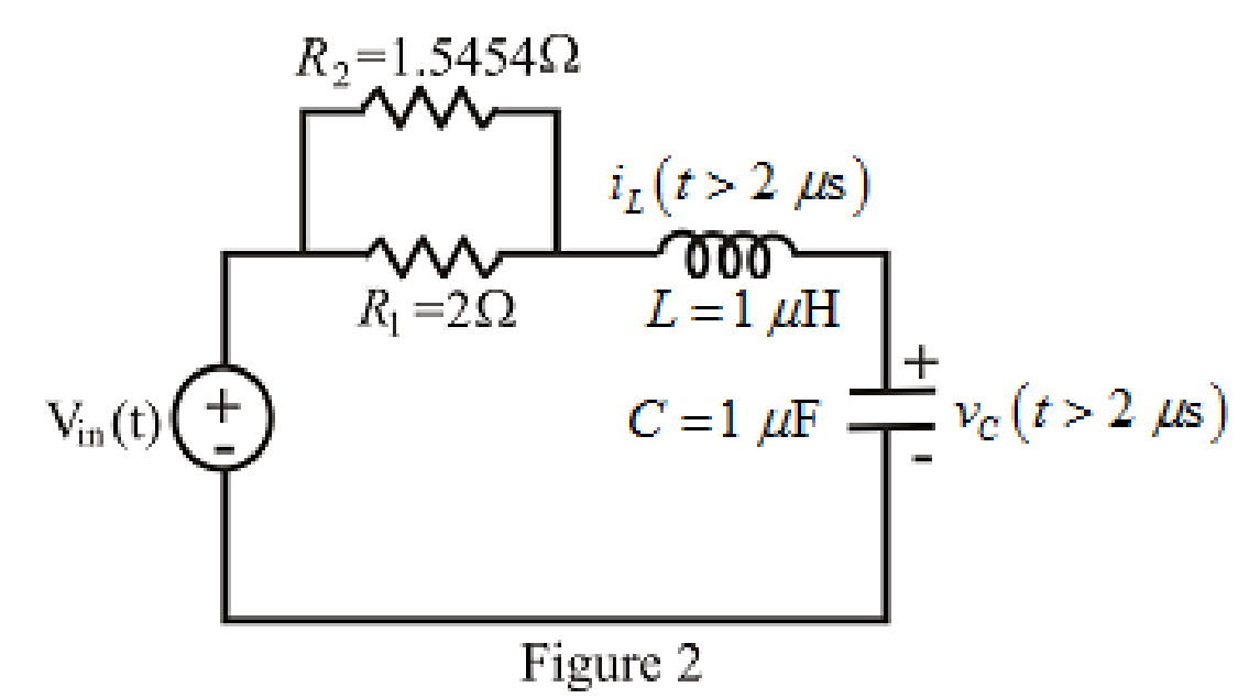
Refer to the redrawn Figure 2:
The initial condition of the voltage across the
Substitute
So, the initial condition of the voltage across the
Substitute
So, the initial condition ofthe current through the
At
The expression for the equivalent resistor when resistors are connected in parallel is as follows:
Here,
So, form equation (15),
Rearrange for
The redrawn circuit diagram is given in Figure 3.
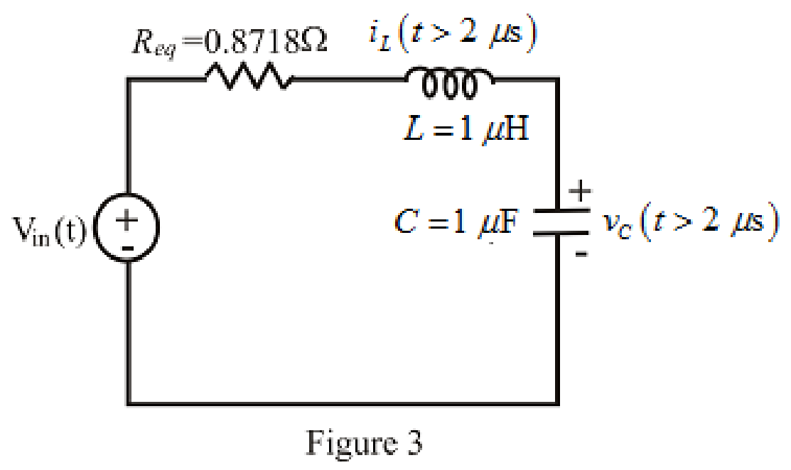
Refer to the redrawn Figure 3:
Substitute
Substitute
Here, the resonant frequency is greater than the exponential damping coefficient.
Therefore, the response of the circuit is under-damped damped.
Substitute
At
Therefore, the value of forced response
Substitute
Apply time shift in equation (18).
Substitute
The initial condition of the voltage across the
Substitute
Rearrange for
The expression for the current flowing through
So, the current flowing through
The expression for the current flowing through the
Here,
Rearrange for
Substitute
Substitute
Substitute
Substitute
Rearrange for
Substitute
Substitute
Substitute
Conclusion:
Thus, the expressions for
Want to see more full solutions like this?
Chapter 9 Solutions
Loose Leaf for Engineering Circuit Analysis Format: Loose-leaf


- 47. Obtain an equation for vc as labeled in the circuit of Fig. 9.50 valid for all t> 0. t = 0 2i + VC 100 2 X. 40 µF 30 Ω 90 mH I FIGURE 9.50 Vc(t) = -2.08e-1188.4986t + 10.48e-233.721tarrow_forwardExample: Find the v(t) and i(t) in the circuit in Figure 9.16 + v = 10 cos 4t 0.1 F = v Figure 9.16arrow_forwardPart (0) Prior to coming to the lab, calculate the theoretical parameter values of S₁, S2, a, wd and T (time period) for the RLC circuit shown in Figure 9.1 and record them in Table 9.1 + 2Vp-p ( Figure 9.1: Series RLC Circuit α Rtot 2009 m Wo 100mH Table 9.1: Theoretical Parameter Values of Figure 9.1 Parameter Calculated Value Wd S₁ S₂ T 39 0.01μFarrow_forward
- Example 9.2-1 (See Example 9.2-1 in the textbook for the solution to a similar problem.) 0.25H 9Ω Ω 0.20H This circuit can be represented by the differential equation d i2 + aoi2. dvs b1 dt + + a1 dt dt2 Determine the values of the coefficients b,, a, and a- |and a, = a1 = b1 Click if you would like to Show Work for this question: Open Show Workarrow_forwardCalculate transient voltage uC(t) after commutation in circuit shown in Fig. 9.12. Assume: R1=1Ω, R2=2Ω,L=1H, C=1F, e(t)=10sin(t).arrow_forward9.42 Calculate vo(t) in the circuit of Fig. 9.49. 50 Ω 30 S2 ww + 50 μF 100 sin 200t V Figure 9.49 For Prob. 9.42. 0.1 H y (1)arrow_forward
- P 9.8-1 Determine i(t) for t> 0 for the circuit shown in Figure P 9.8-1. 11 mA 1=0 Figure P 9.8-1 M 3 ΚΩ 1 ΚΩ 6.25 H + Uc=1 μF 5 Varrow_forwardR1 w C1 1E-4 1E-8 e. For R1200 Q determine the voltage across the capacitor as a function of time for t>0. Note may have to use F(1) instead of F(0). Note: Non-zero initial condition! V1-10V 1<0 8V DOarrow_forwarddy The non-homogeneous differential equation dx x + y+4 can be solved by putting 9x + 9y + 6 v = 4x + 9y v = 4x + 4y v = x + Y v = 4x – 9yarrow_forward
- 4) The function sin x (which you may remember from Calculus 1 limits) is important in signal processing and electrical engineering, and is known as the "sinc" function, often abbreviated as just sinc(x). Find § sinc(x) dx. Then, approximate ſ sinc(x) dx using the first five terms of the appropriate series.arrow_forwarddont use others answers show your work step by step 9) Write an expression for the complement of F if F(x,y,z) = (x'+y)(x+z)(y'+z)'arrow_forwardH.w. Derive a second order DE for the curvent i(t) tigure (4). as skown in Rarrow_forward
 Introductory Circuit Analysis (13th Edition)Electrical EngineeringISBN:9780133923605Author:Robert L. BoylestadPublisher:PEARSON
 Delmar's Standard Textbook Of ElectricityElectrical EngineeringISBN:9781337900348Author:Stephen L. HermanPublisher:Cengage Learning
 Programmable Logic ControllersElectrical EngineeringISBN:9780073373843Author:Frank D. PetruzellaPublisher:McGraw-Hill Education
 Fundamentals of Electric CircuitsElectrical EngineeringISBN:9780078028229Author:Charles K Alexander, Matthew SadikuPublisher:McGraw-Hill Education
 Electric Circuits. (11th Edition)Electrical EngineeringISBN:9780134746968Author:James W. Nilsson, Susan RiedelPublisher:PEARSON
 Engineering ElectromagneticsElectrical EngineeringISBN:9780078028151Author:Hayt, William H. (william Hart), Jr, BUCK, John A.Publisher:Mcgraw-hill Education,