
Videos
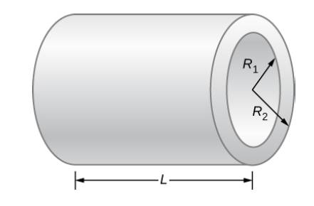
Consider a resistor made from a hollow cylinder of carbon as shown below. The inner radius of the cylinder is Ri= 0.20 mm and the outer radius is R0 = 0.30 mm. The length of the resistor is L = 0.90 mm. The resistivity of the carbon is
Want to see the full answer?
Check out a sample textbook solution
Chapter 9 Solutions
University Physics Volume 2
Additional Science Textbook Solutions
Glencoe Physical Science 2012 Student Edition (Glencoe Science) (McGraw-Hill Education)
Physics for Scientists and Engineers: A Strategic Approach with Modern Physics (4th Edition)
An Introduction to Thermal Physics
Essential University Physics: Volume 1 (3rd Edition)
Modern Physics
College Physics (10th Edition)


- 1.00 µF, R = 2.00 x 10° Q, and Ɛ = 10.0 V. At the instant 16.2 s after the switch is closed, The values of the components in a simple series RC circuit containing a switch (see figure below) are C = calculate the following. %3D S R (a) the charge on the capacitor q : µC (b) the current in the resistor I = nA (c) the rate at which energy is being stored in the capacitor rate = nW (d) the rate at which energy is being delivered by the battery Poattery nWarrow_forwardIn the shown circuit, the capacitor is initially uncharged. The switch S is closed at time t=0. Find the current in the circuit (in uA) when the charge on the capacitor is 8.3 uC. 10 V =20 uF 0.05 MOarrow_forwardR1 is 150 ohms, and R2 is 220 ohms. (150 +220 = 370). In a series circuit, the current is the same across the circuit. The available power storage is 6 volts. The problem I am have is conceptualizing what V1 + V2 equals. I conjecture that the sum would be less than 6 V. I can't say 3 + 3 =6 V, but rather V1 + V2 < 6? Unless R1=R2, then perhaps 3 + 3 = 6V. However, R1 is 150 ohms, and R2 is 220 ohms. Complicating issue, if I use an ammeter and voltmeter, these devices may have some internal resistance, so equals becomes < 6 V? How then do I conceptualize better, V1 + V2, so that maybe it is based on the value of the individual Resistor?arrow_forward
- Consider following circuit with R1 = 62 Ω, R2 = 11 Ω, R3 = 62 / 10 Ω, R4 = 11/10 Ω and and ξ=11 V i. Cross sections through two long conductors of the same length and material, with square crosssections of edge lengths are shown below. Conductor Y fits snugly within conductor X, Rank theresistance of X and Y?arrow_forwardA series circuit consists of a resistor and capacitor of resistance R ohms and capacitance C Farads. It has the battery as a source of E volts. When the switch is closed the capacitor begins to charge and the total charge on the capacitor at any time q (t) is governed by: dq(t)/dt+(1/RC)q(t)=E/R where R, C, E are taken as constant. Find the charge q (t) across the capacitor at any time t. Hence show that as t → ∞, E = q(t)/c (Note that at t=0,q(t)=0)arrow_forwardThe emf source, ε=4.5 V, of the circuit shown in the figure has negligible internal resistance. The resistors have resistances R1=2 Ω and R2=4.7 Ω. The capacitor has a capacitance C=4.9 μF. Determine the time constant τ, in units of microseconds, for charging the capacitor. What is the charge Q on the capacitor in units of microcoulomb?arrow_forward
- In the figure. take R 1 = 102 Ω, R 2 = 71 Ω, R 3 = 60 Ω, R 4 = 28 Ω, R 5 = 127 Ω and ΔV 1 = 146 V, ΔV 2 = 29 V. Calculate the magnitude of the current in R 5 resistor. (Your result must be in Amperes. Include 3 digit after the decimal point and maximum of 5% of error is accepted in your answer.)arrow_forwardThe voltage V in a simple electrical circuit is slowly decreasing as the battery wears out. The resistance R is slowly increasing as the resistor heats up. Use Ohm's Law, V = IR, to find how the current I is changing at the moment when R = 356 Ω, I = 0.02 A, dV/dt = −0.01 V/s, and dR/dt = 0.06 Ω/s. (Round your answer to six decimal places.)arrow_forwardThe current, I, is 2A through R2=4Ω and V1=6.00V. Determine the current through R1 =2Ω and R3=5Ω and the voltage V2 for the given circuit.arrow_forward
- To get the maximum current, the connection should be in parallel. If you create a parallel connection with 30V DC source and three resistors with R1 = 50Ω, R2 = 75Ω, and R3 = 100Ω, how do you calculate for the total current (IT) and the current flowing in each resistor (I1, I2, I3), and the total voltage (VT) and the voltage across each resistor (V1, V2, V3)? How do you also determine the power dissipated by each resistor (P1, P2, P3) and by the whole circuit (PT)??arrow_forwardDetermine the admittance Y for the circuit given in the figure. Take R= 4 Q. Y =-j10 2 ER The admittance Yis [ |)) mS. + wwarrow_forwardTo get the minimum current, the connection should be in series. If you create a series connection with 30V DC source and three resistors with R1 = 50Ω, R2 = 75Ω, and R3 = 100Ω, how do you calculate for the total current (IT) and the current flowing in each resistor (I1, I2, I3), and the total voltage (VT) and the voltage across each resistor (V1, V2, V3)? How do you also determine the power dissipated by each resistor (P1, P2, P3) and by the whole circuit (PT)??arrow_forward
 College PhysicsPhysicsISBN:9781305952300Author:Raymond A. Serway, Chris VuillePublisher:Cengage Learning
 University Physics (14th Edition)PhysicsISBN:9780133969290Author:Hugh D. Young, Roger A. FreedmanPublisher:PEARSON
 Introduction To Quantum MechanicsPhysicsISBN:9781107189638Author:Griffiths, David J., Schroeter, Darrell F.Publisher:Cambridge University Press
 Physics for Scientists and EngineersPhysicsISBN:9781337553278Author:Raymond A. Serway, John W. JewettPublisher:Cengage Learning
 Lecture- Tutorials for Introductory AstronomyPhysicsISBN:9780321820464Author:Edward E. Prather, Tim P. Slater, Jeff P. Adams, Gina BrissendenPublisher:Addison-Wesley
 College Physics: A Strategic Approach (4th Editio...PhysicsISBN:9780134609034Author:Randall D. Knight (Professor Emeritus), Brian Jones, Stuart FieldPublisher:PEARSON