
(a)
The value of the output resistance.
(a)
Answer to Problem 11.70P
The value of the output resistance
Explanation of Solution
Given:
The given diagram is shown in Figure 1

Figure 1
Calculation:
The expression for the input current is given by,
The expression to determine the value of the transconductance is given by,
The expression for the relation for the voltage for hybrid pie parameter.
Substitute
The value of the collector current
The value of the collector current
The expression to determine the expression for the diffusion resistance is given by,
Substitute
The value of the transconductance is calculated as,
Substitute
The expression to determine the value of the resistance
Substitute
The expression to determine the expression for the diffusion resistance is given by,
Substitute
The value of the transconductance is calculated as,
Substitute
The expression to determine the value of the resistance
Substitute
Substitute
The expression for the input current
Substitute
Substitute
The expression to determine the output resistance is given by,
Substitute
The value of the quiescent current is given by,
The small signal output resistance is calculated as,
The value of the output resistance is calculated as,
Conclusion:
Therefore, the value of the output resistance
(b)
The value of the differential mode voltage gain.
(b)
Answer to Problem 11.70P
The value of the differential voltage gain is
Explanation of Solution
Given:
The given diagram is shown in Figure 1
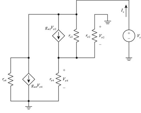
Figure 1
Calculation:
The required small signal circuit is shown in Figure 2
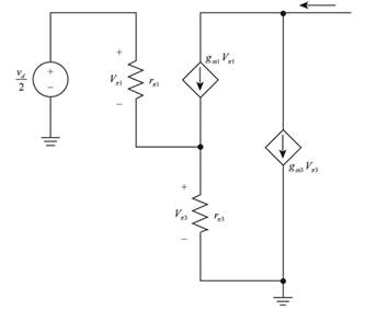
Figure 2
The expression for the transconductance is given by,
The expression for the differential voltage gain is given by,
The expression for the change in current is given by,
Consider the value of
Substitute the values in the above equation.
Substitute
Substitute
Substitute
Substitute
The value of gain is given by,
The expression for the input resistor is given by,
The value of expression for the differential input resistor is calculated as,
Conclusion:
Therefore, the value of the differential voltage gain is
(c)
The value of the differential mode input resistance
(c)
Answer to Problem 11.70P
The value of
Explanation of Solution
Given:
The given diagram is shown below.

Calculation:
The expression for the input resistor is given by,
The value of expression for the differential input resistor is calculated as,
Conclusion:
Therefore, the value of
Want to see more full solutions like this?
Chapter 11 Solutions
Microelectronics: Circuit Analysis and Design

- Q1. a. In your own words, explain finite output resistance in MOSFET's saturation b. In your own words, explain the boundary between Triode and Saturation in MOSFET?arrow_forwardc. For the circuit shown in Figure, determine lc and VCB. Assume the transistor to be made of Silicon. Ic RE=1.6 kn Rc=1.1 kn EE=8 V Vcc= 20 varrow_forwardQUESTION 12: The differential amplifier shown in Figure P11.60 has a pair of pnp bipolars as input devices and a pair of npn bipolars connected as an active load. The circuit is biased by Io=0.24 mA, and the transistor parameters are ß = 80 , VẬP=90 V, and VAN = 115 V. (a) Determine Io such that the de currents in the diff-amp are balanced. (b) Find the open-circuit differential-mode voltage gain. (c) Determine the differential-mode voltage gain if a load resistance R1 = 260 k2 is connected to the output. Io (HA) Format : 4.595 Ad (open circuit) Format : 4594.5 Ag (closed loop) Format : 796.4 V+ Q2 Oa 어 RL Q3 Q4 V-arrow_forward
- A. Detemine the value of the collector resistor in an npn transistor amplifier with Bpc = 250, VBB = 2.5 V, Vcc = 9 V, VCE = 4 V, and Rg = 100 k2. B. Detemine Ic(sat) for the transistor in below Figure. What is the value of Is necessary to produce saturation? What minimum value of VIN is necessary for saturation? Assume VCE(sat) = 0 V. %3D +5 V 10 kN Rg VINO BDC = 150 1.0 MNarrow_forwardA Bipolar junction Transistor with curreat amplification factor being 100, Input Base current is 50μA. Collector voltage is 10 V and biasing voltage being +20 V. Find followings a. Collector current b. Resistance (R1) c. Collector voltage , Emitter voltage , Base Voltage & Collector-Emitter Voltage.arrow_forwardDiagram show biasing by feedback resistor method.Calculate (i) collector current, and (ii) collector voltage, Given that ß = 100 and transistor is made of sillicon.arrow_forward
- (ii) What is IEEE519 standard? Explain the significance of the terms PCC, Isc and I used in this standard. Describe the maximum harmonics current distortion in % of I for individual harmonic order prescribed by this standard.arrow_forward1. For the circuit in Figure 1: a) Calculate the input and output power if the input signal results in a base current of 6 mA. b) Calculate the input power dissipated by the circuit if Re is changed to 2kn. c) What maximum output power can be delivered by the circuit if Rg is changed to 2 ko? d) If the circuit is biased at its center voltage and center collector operating point, what is the input power for a maximum output power of 2W? 20V Re = 16 2 1.2 ks2 B- 40 100 µF Figure 1arrow_forward(a). If the current gain is 100 and the collector current is 10 mA, the base current is?arrow_forward
- Design a collector to bias circuit for the specification given below. Vcc=13 volt Vce=5 v β =98 Ic= 5maarrow_forwarda) Calculate the VA voltage value.b) Given the input voltage (Vin) waveformin the above Op-amp circuit, Vtl (low)and Vtu (high) hysteresis crossoverCalculate the voltages. c) At the Vtl and Vtu transitions of the Vo voltageCalculate the position changes.arrow_forwardA) Find and draw the equivalent re circuit model. Calculate the voltage gain.arrow_forward
 Introductory Circuit Analysis (13th Edition)Electrical EngineeringISBN:9780133923605Author:Robert L. BoylestadPublisher:PEARSON
 Delmar's Standard Textbook Of ElectricityElectrical EngineeringISBN:9781337900348Author:Stephen L. HermanPublisher:Cengage Learning
 Programmable Logic ControllersElectrical EngineeringISBN:9780073373843Author:Frank D. PetruzellaPublisher:McGraw-Hill Education
 Fundamentals of Electric CircuitsElectrical EngineeringISBN:9780078028229Author:Charles K Alexander, Matthew SadikuPublisher:McGraw-Hill Education
 Electric Circuits. (11th Edition)Electrical EngineeringISBN:9780134746968Author:James W. Nilsson, Susan RiedelPublisher:PEARSON
 Engineering ElectromagneticsElectrical EngineeringISBN:9780078028151Author:Hayt, William H. (william Hart), Jr, BUCK, John A.Publisher:Mcgraw-hill Education,