
Videos
a.
The small-signal voltage gain
a.
Answer to Problem 11.84P
Explanation of Solution
Given:
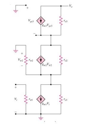
The given circuit is,
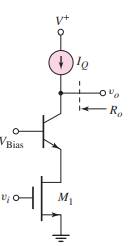
The two amplifying transistors
Calculation:
Consider the given figure,
Now find trans-conductance,
Now calculate
Now consider small-signal equivalent circuit,
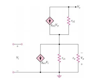
Apply nodal method at node
Now apply nodal method at node
Now consider,
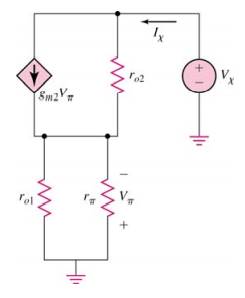
Find
Apply nodal analysis at node
Hence,
b.
The small-signal voltage gain
b.
Answer to Problem 11.84P
Explanation of Solution
Given:
The given circuit is,
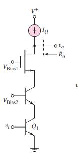
The two amplifying transistors
Calculation:
Consider the given figure,
Now find trans-conductance,
Now,
Now consider circuit,
Apply nodal at top part of the circuit,
Apply nodal at middle part of the circuit,
Find
Apply nodal analysis at node
Hence,
Want to see more full solutions like this?
Chapter 11 Solutions
Microelectronics: Circuit Analysis and Design


- Draw, Illustrate and label your schematic diagram before solving the problem. 1) Given a Fixed-Biased transistor circuit with Beta DC is 200 , voltage at common collector is +22v ,base supply voltage is +11V, Base resistor is 47kOhms , collector resistor is 390 ohms ,Voltage at Base-emitter junction is 0.7v. Determine the Q-point of collector current and Voltage at collector-emitter junction. These might be help as a guide to solve the problem.arrow_forwardQa: A transistor dissipates 50W in an ambient temperature of 60°C, the thermal resistances are 0-0.5 °CW¹, 8ca-4 °CW. Determine the junction temperature without a heat sink. Determine the thermal resistance of the heat sink to avoid the junction temperature exceeding 180°C. )arrow_forwardInstruction/s: Draw, Illustrate and label your schematic diagram before solving the problem. 1.) Given a Fixed-Biased transistor circuit with Beta DC is 200 , voltage at common collector is +22v ,base supply voltage is +11V, Base resistor is 47kOhms , collector resistor is 390 ohms ,Voltage at Base-emitter junction is 0.7v. Determine the Q-point of collector current and Voltage at collector-emitter junction. These is the example or guide that might help in answering the problem.arrow_forward
- Name: (11) The supply voltage VCC equals 9V. The base resistor RB is 42. Take 0.6V for the knee voltage of the base-emitter diode. Draw the load line for a short-circuit current of 15mA (a) What is the value of the collector resistor RC in that case? (b) What is then the voltage Va across the transistor? (c) What is then the current le through the transistor? RB www VCC 9.0V RC Ic (mA) 15 D 10 Student nr. saturation region 5 Answers: (a) RC- (b) Va (c) Ic= active region (12) Same circuit and transistor as above, but now with a short- scircuit current of 5 mA. Draw the new load line. (a) What is the value of the collector resistor RC in that case? (b) What is then the voltage Vc across the transistor? (c) What is then the current Ic through the transistor? cutoff region 10 15 VCE (V) {npn} 20 Answers: (a) RC = (b) VCE= (c) Ic= L₂=0.4 mA 1₁-0.3 mA IB=0.2 mA Ig=0.1mA Ig=0 mAarrow_forwardA certain npn silicon transistor has vBE=0.7 V for iB=0.1 mA at a temperature of 30°C. Sketch the input characteristic to scale at 30°C. What is the approximate value of vBE for iB = 0.1 mA at 180°C? (Use the rule of thumb that vBE is reduced in magnitude by 2 mV per degree increase in temperature.) Sketch the input characteristic to scale at 180°C.arrow_forwardGiven a D-MOSFET circuit used as an amplifier with the following parameter: IDSS=12mA and a transconductance of gm=3.2 mS. Determine the DC drain to source voltage VDS and the AC output voltage if Vin=500 mV.arrow_forward
- Transistors originally were made with germanium but modern transistors use silicon for its higher heat tolerance. Transistors amplify and switch signals. They can be analog or digital. Two prevalent transistors today are Metal-Oxide-Semiconductor Field Effect Transistors (MOSFET) and Bipolar Junction Transistors (BJT).In your own understanding in the field of electronics can you compare and contrast which one has merit over the other ?arrow_forwarda) The n-channel JFET and the D-MOSFET have very similar I-V output characteristics. Which of these two structures can be operated in enhancement mode and why is that possible?arrow_forwardFrom the circuit, a. What is VCE when VIN = 0b. What minimum value of IB will saturate the transistorc. Calculate the maximum value of RB when the input voltage is 5V.Please explain the steps.arrow_forward
- 1. For the circuit shown below, VBE = 0.7 V, VCE-Sat = 0.2 V. Determine the following: a. The operating region of the transistor (cut-off, active, saturation) b. The ratio of the collector current to the base current. RB = 50 kQ ww *5.7 V Rc=1kQ B=200 10 V wwwarrow_forwardTo operate as an amplifier, it is the base of an npn transistor... Please select one: a. 0V b. positive by collector c. negative relative to emitter d. positive relative to emitterarrow_forwardMost of the following statements about integrated circuits arecorrect, but one is not. Which statement is NOT true? Select one: a. Transistors are constructed in a small area of an integrated circuit,and are connected to other transistors by wires that are embedded inthe integrated circuit b. Wires that carry signals may be embedded in a substrate without a shortcircuit because a short circuit would require a signal to cross areverse biased junction c. Each transistor on an integrated circuit is manufactured individually,one at a time d. An integrated circuit contains several layersarrow_forward
 Introductory Circuit Analysis (13th Edition)Electrical EngineeringISBN:9780133923605Author:Robert L. BoylestadPublisher:PEARSON
 Delmar's Standard Textbook Of ElectricityElectrical EngineeringISBN:9781337900348Author:Stephen L. HermanPublisher:Cengage Learning
 Programmable Logic ControllersElectrical EngineeringISBN:9780073373843Author:Frank D. PetruzellaPublisher:McGraw-Hill Education
 Fundamentals of Electric CircuitsElectrical EngineeringISBN:9780078028229Author:Charles K Alexander, Matthew SadikuPublisher:McGraw-Hill Education
 Electric Circuits. (11th Edition)Electrical EngineeringISBN:9780134746968Author:James W. Nilsson, Susan RiedelPublisher:PEARSON
 Engineering ElectromagneticsElectrical EngineeringISBN:9780078028151Author:Hayt, William H. (william Hart), Jr, BUCK, John A.Publisher:Mcgraw-hill Education,