
Fundamentals of Electric Circuits
6th Edition
ISBN: 9780078028229
Author: Charles K Alexander, Matthew Sadiku
Publisher: McGraw-Hill Education
expand_more
expand_more
format_list_bulleted
Videos
Textbook Question
Chapter 13.2, Problem 1PP
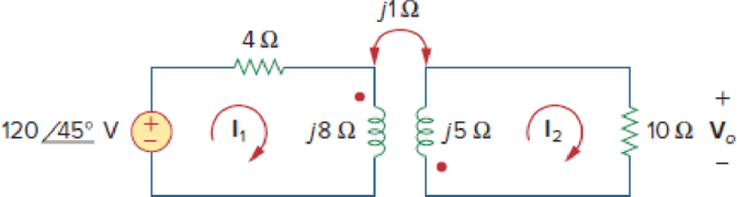
Determine the voltage Vo in the circuit of Fig. 13.10.
Figure 13.10
For Practice Prob. 13.1.
Expert Solution & Answer
Want to see the full answer?
Check out a sample textbook solution
Students have asked these similar questions
Example:
For the circuit shown in Figure below find;
a) The value of R1 for maximum power transfer.
b) The maximum output power.
( Ans. 9 Ω, 13.44W)
R,
R3
R4
2Ω a
R2
12 Q
E
R
12V
2A
b
Solution:
13.5 Draw the output voltage waveform for each circuit below with respect to its input. Indicate the voltage
levels.
+1 V
+1 V
-I V
out
+2 V
Vurtmax) = ±8 V
%3D
Voutomax) = ±10 V
-2 V
(a)
(b)
OV
+ 2 V
(7
741
Output. V,
3
Input, V,
V-
(a)
FIG. 13.2
Chapter 13 Solutions
Fundamentals of Electric Circuits
Ch. 13.2 - Determine the voltage Vo in the circuit of Fig....Ch. 13.2 - Determine the phasor currents I1 and I2 in the...Ch. 13.3 - Prob. 3PPCh. 13.4 - Find the input impedance of the circuit in Fig....Ch. 13.4 - For the linear transformer in Fig. 13.26(a), find...Ch. 13.4 - Solve the problem in Example 13.1 (see Fig. 13.9)...Ch. 13.5 - The primary current to an ideal transformer rated...Ch. 13.5 - In the ideal transformer circuit of Fig. 13.38,...Ch. 13.5 - Find Vo in the circuit of Fig. 13.40. Figure 13.40...Ch. 13.6 - Refer to Fig. 13.43. If the two-winding...
Ch. 13.6 - In the autotransformer circuit of Fig. 13.45, find...Ch. 13.7 - Prob. 12PPCh. 13.8 - Prob. 13PPCh. 13.9 - Refer to Fig. 13.61. Calculate the turns ratio...Ch. 13.9 - Calculate the turns ratio of an ideal transformer...Ch. 13.9 - In Example 13.17, if the eight 100-W bulbs are...Ch. 13 - Refer to the two magnetically coupled coils of...Ch. 13 - Prob. 2RQCh. 13 - Prob. 3RQCh. 13 - Prob. 4RQCh. 13 - The ideal transformer in Fig. 13.70(a) has N2/N1 =...Ch. 13 - Prob. 6RQCh. 13 - A three-winding transformer is connected as...Ch. 13 - Prob. 8RQCh. 13 - Prob. 9RQCh. 13 - Prob. 10RQCh. 13 - For the three coupled coils in Fig. 13.72,...Ch. 13 - Using Fig. 13.73, design a problem to help other...Ch. 13 - Two coils connected in series-aiding fashion have...Ch. 13 - (a) For the coupled coils in Fig. 13.74(a), show...Ch. 13 - Two coils are mutually coupled, with L1 = 50 mH,...Ch. 13 - Given the circuit shown in Fig. 13.75, determine...Ch. 13 - For the circuit in Fig. 13.76, find Vo. Figure...Ch. 13 - Find v(t) for the circuit in Fig. 13.77.Ch. 13 - Prob. 9PCh. 13 - Find vo in the circuit of Fig. 13.79. Figure 13.79...Ch. 13 - Use mesh analysis to find ix in Fig. 13.80, where...Ch. 13 - Determine the equivalent Leq in the circuit of...Ch. 13 - For the circuit in Fig. 13.82, determine the...Ch. 13 - Obtain the Thevenin equivalent circuit for the...Ch. 13 - Find the Norton equivalent for the circuit in Fig....Ch. 13 - Obtain the Norton equivalent at terminals a-b of...Ch. 13 - In the circuit of Fig. 13.86, ZL is a 15-mH...Ch. 13 - Find the Thevenin equivalent to the left of the...Ch. 13 - Determine an equivalent T-section that can be used...Ch. 13 - Determine currents I1, I2, and I3 in the circuit...Ch. 13 - Prob. 21PCh. 13 - Find current Io in the circuit of Fig. 13.91.Ch. 13 - Let is = 5 cos (100t) A. Calculate the voltage...Ch. 13 - In the circuit of Fig. 13.93, (a) find the...Ch. 13 - Prob. 25PCh. 13 - Find Io in the circuit of Fig. 13.95. Switch the...Ch. 13 - Find the average power delivered to the 50-...Ch. 13 - In the circuit of Fig. 13.97, find the value of X...Ch. 13 - Prob. 29PCh. 13 - (a) Find the input impedance of the circuit in...Ch. 13 - Using Fig. 13.100, design a problem to help other...Ch. 13 - Two linear transformers are cascaded as shown in...Ch. 13 - Determine the input impedance of the air-core...Ch. 13 - Using Fig. 13.103, design a problem to help other...Ch. 13 - Find currents I1, I2, and I3 in the circuit of...Ch. 13 - As done in Fig. 13.33, obtain the relationships...Ch. 13 - A 2402,400-V rms step-up ideal transformer...Ch. 13 - Design a problem to help other students better...Ch. 13 - A 1,200240-V rms transformer has impedance on the...Ch. 13 - The primary of an ideal transformer with a turns...Ch. 13 - Given I2 = 2 A, determine the value of Is in Fig....Ch. 13 - For the circuit in Fig. 13.107, determine the...Ch. 13 - Obtain V1 and V2 in the ideal transformer circuit...Ch. 13 - In the ideal transformer circuit of Fig. 13.109,...Ch. 13 - For the circuit in Fig. 13.110, find the value of...Ch. 13 - (a) Find I1 and I2 in the circuit of Fig. 13.111...Ch. 13 - Prob. 47PCh. 13 - Using Fig. 13.113, design a problem to help other...Ch. 13 - Find current ix in the ideal transformer circuit...Ch. 13 - Prob. 50PCh. 13 - Use the concept of reflected impedance to find the...Ch. 13 - For the circuit in Fig. 13.117, determine the...Ch. 13 - Refer to the network in Fig. 13.118. (a) Find n...Ch. 13 - A transformer is used to match an amplifier with...Ch. 13 - For the circuit in Fig. 13.120, calculate the...Ch. 13 - Find the power absorbed by the 100- resistor in...Ch. 13 - For the ideal transformer circuit of Fig. 13.122...Ch. 13 - Determine the average power absorbed by each...Ch. 13 - In the circuit of Fig. 13.124, let vs = 165...Ch. 13 - Refer to the circuit in Fig. 13.125 on the...Ch. 13 - For the circuit in Fig. 13.126, find Il, I2, and...Ch. 13 - For the network in Fig. 13.127, find: (a) the...Ch. 13 - Find the mesh currents in th circuit of Fig....Ch. 13 - For the circuit in Fig. 13.129. find the turns...Ch. 13 - Calculate the average power dissipated by the 20-...Ch. 13 - Design a problem to help other students better...Ch. 13 - An autotransformer with a 40 percent tap is...Ch. 13 - In the ideal autotransformer of Fig. 13.131,...Ch. 13 - In the circuit of Fig. 13.131, N1 = 190 turns and...Ch. 13 - In the ideal transformer circuit shown in Fig....Ch. 13 - When individuals travel, their electrical...Ch. 13 - In order to meet an emergency, three single-phase...Ch. 13 - Figure 13.135 on the next page shows a three-phase...Ch. 13 - Consider the three-phase transformer shown in Fig....Ch. 13 - A balanced three-phase transformer bank with the...Ch. 13 - Using Fig. 13.138, design a problem to help other...Ch. 13 - The three-phase system of a town distributes power...Ch. 13 - Use PSpice or MultiSim to determine the mesh...Ch. 13 - Use PSpice or MultiSim to find I1, I2, and I3 in...Ch. 13 - Prob. 80PCh. 13 - Use PSpice or MultiSim to find I1, I2, and I3 in...Ch. 13 - A stereo amplifier circuit with ail output...Ch. 13 - A transformer having 2,400 turns on the primary...Ch. 13 - A radio receiver has an input resistance of 300 ....Ch. 13 - A step-down power transformer with a turns ratio...Ch. 13 - A 240120-V rms power transformer is rated at 10...Ch. 13 - A 4-kVA, 2,400240-V rms transformer has 250 turns...Ch. 13 - A 25,000240-V rms distribution transformer has a...Ch. 13 - A 4,800-V rms transmission line feeds a...Ch. 13 - A four-winding transformer (Fig. 13.146) is often...Ch. 13 - A 440/110-V ideal transformer can be connected to...Ch. 13 - Ten bulbs in parallel are supplied by a 7,200120-V...
Additional Engineering Textbook Solutions
Find more solutions based on key concepts
What is the color code for a 365- five-band precision resistor with a tolerance of 5 percent?
ELECTRICITY FOR TRADES (LOOSELEAF)
Electric power systems provide energy in a variety of commercial and industrial settings. Make a list of system...
Principles and Applications of Electrical Engineering
The voltage source of the circuit shown in Fig. P1.29 is given by s(t)=25cos(4104t45)(V). Obtain an expression ...
Fundamentals of Applied Electromagnetics (7th Edition)
How many coulombs do 93.8 1016 electrons represent?
Principles Of Electric Circuits
Three point charges of equal magnitude q, that will yield a zero net electric field at the origin.
Engineering Electromagnetics
With respect to the circuit in Fig. 5.90, (a) employ Thévenin’s theorem to determine the equivalent network see...
Loose Leaf for Engineering Circuit Analysis Format: Loose-leaf
Knowledge Booster


Learn more about
Need a deep-dive on the concept behind this application? Look no further. Learn more about this topic, electrical-engineering and related others by exploring similar questions and additional content below.Similar questions
- For the circuit shown in Figure below find; a) The value of RL for maximum power transfer. b) The maximum output power. (Ans. 9 Ω, 13.44W) R R3 3Ω R4 2Ω a R2 12 ΩΣ E RL 12V 2Aarrow_forwardDetermine the value of the Current 13. +1 12 V + - www 892 O A. 0.44 Amps OB. 1.05 Amps OC. 0.15 Amps O D. 0.45 Amps OE. 0.35 Amps + 9 V - www 20 92 13arrow_forwardQ.1. A power suppply having 220 V AC input and two fixed outputs as 10 V DC and 20 V DC is requested from you. For this purpose, a transformer with 220 V AC input / 15 V AC output, some capacitors, some silicon diodes, and zener diodes are presented.a) Design your power supply and point out DC voltage outputs b) Explain the operation of the network and all the components used in the design .c) Calculate and plot input and output signals of the network.Hint: For design, remember clipper, clamper, rectifier,voltage multiplier and zener circuitsarrow_forward
- Design a half- / full-wave AC to DC single-phase converter circuit to produce an average output voltage of 10 V across a 50 Ω resistor from a source of 200 V. Also, determine the power absorbed by the resistor.arrow_forwardDiscussion 1. In your own words, state Kirchhoff's Voltage and Current law? 2. For the circuit shown in Fig.3. If 1,=18 mA and L-4.5 mA, then /, is: a. 5.3mA b. 13.1mA 3. If other resistors values are used for the circuit of Fig.2a in loop A, so that: V-0.54V and v-3.58V, Then Ve should be: a. 1016V 4. The current i, in the circuit Fig .4 is 4A find i, iz, i3, ii and ig „Viand V2. c. 7,8mA d. 9 mA b. 10.88V c. 107V d. 4,74V Univensitnfiut neering 1.2 KO 330 0 2.2 KO 2 KO 2 KO 1640 O Fig.3 ELECTRIC 25 Q 50 10 Q V 80 180 V Fig.4arrow_forwardDesign a half-wave AC to DC single-phase converter circuit to produce an average output voltage of 10 V across a 50 Ω resistor from a source of 200 V. Also, determine the power absorbed by the resistor.arrow_forward
- 2. Draw a circuit schematic indicating how you will connect your DC power supply to provide +8 V, -8 V and a 0 V common. 3. Draw a circuit schematic (including IC pin numbers and bypass capacitors) for Part A, D, E being sure to note which resistor values you will be using (this may require calculations in advance). 4. Design matrix for digital-to-analog converterarrow_forwardA Pulley is an example of active amplifier. Select one: O a. True O b. False A sinusoidal voltage v = (10 sin 377t) V rm.s is applied to a resistor of 50 Q. The avera Select one: ONone of the Answers O0.2 W O20 W 2Warrow_forwardAs shown in the circuit below, a transformer is used to match an amplifier with an 8-ohm load. The Thevenin equivalent of the amplifier is Vth = 10 V, Zth = 128 ohms. What is the required turns ratio n for maximum power transfer? 1:n Amplifier circuit ell 892arrow_forward
- Q.) The circuit shown below is an idealized forward converter. Assuming an input voltage Vd=40V, duty cycle of 0.5 and an output power of 50W with a resistive load of 50Ω. What is the transformer ratio, N1:N2 of this converter ?arrow_forwardA bridge rectifier is connected to a transformer which takes 230V 50Hz at its input, and supplies a loadof 200 Ω. If the turns ratio of the transformer is 4:1 what will be the output voltage (DC), the peakinverse voltage and the output frequency.arrow_forwardDesign a DC voltage source to maintain fixed, stable 15 V, 13.6 V and 12.2 V DC voltages to different loads. In order to realize this request, a transformer having a primer voltage 220 V AC and a seconder voltage 27 V AC (220/27 V AC transformer), some silicon diodes, zener diode and some resistors of 1.5 k2 can be considered in design. a) Draw the network b) Explain the tasks of each component and overall operation in your design. c) Calculate load current and power dissipation for zener diodearrow_forward
arrow_back_ios
SEE MORE QUESTIONS
arrow_forward_ios
Recommended textbooks for you
 Introductory Circuit Analysis (13th Edition)Electrical EngineeringISBN:9780133923605Author:Robert L. BoylestadPublisher:PEARSON
 Delmar's Standard Textbook Of ElectricityElectrical EngineeringISBN:9781337900348Author:Stephen L. HermanPublisher:Cengage Learning
 Programmable Logic ControllersElectrical EngineeringISBN:9780073373843Author:Frank D. PetruzellaPublisher:McGraw-Hill Education
 Fundamentals of Electric CircuitsElectrical EngineeringISBN:9780078028229Author:Charles K Alexander, Matthew SadikuPublisher:McGraw-Hill Education
 Electric Circuits. (11th Edition)Electrical EngineeringISBN:9780134746968Author:James W. Nilsson, Susan RiedelPublisher:PEARSON
 Engineering ElectromagneticsElectrical EngineeringISBN:9780078028151Author:Hayt, William H. (william Hart), Jr, BUCK, John A.Publisher:Mcgraw-hill Education,
Introductory Circuit Analysis (13th Edition)
Electrical Engineering
ISBN:9780133923605
Author:Robert L. Boylestad
Publisher:PEARSON
Delmar's Standard Textbook Of Electricity
Electrical Engineering
ISBN:9781337900348
Author:Stephen L. Herman
Publisher:Cengage Learning
Programmable Logic Controllers
Electrical Engineering
ISBN:9780073373843
Author:Frank D. Petruzella
Publisher:McGraw-Hill Education
Fundamentals of Electric Circuits
Electrical Engineering
ISBN:9780078028229
Author:Charles K Alexander, Matthew Sadiku
Publisher:McGraw-Hill Education
Electric Circuits. (11th Edition)
Electrical Engineering
ISBN:9780134746968
Author:James W. Nilsson, Susan Riedel
Publisher:PEARSON
Engineering Electromagnetics
Electrical Engineering
ISBN:9780078028151
Author:Hayt, William H. (william Hart), Jr, BUCK, John A.
Publisher:Mcgraw-hill Education,
Mesh Current Problems in Circuit Analysis - Electrical Circuits Crash Course - Beginners Electronics; Author: Math and Science;https://www.youtube.com/watch?v=DYg8B-ElK0s;License: Standard Youtube License