
Concept explainers
Videos
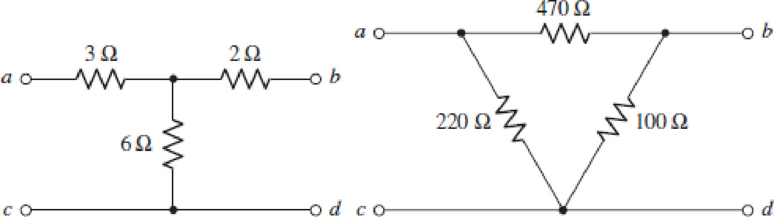
The two-port networks of Fig. 16.50 are connected in series. (a) Determine the impedance parameters for the series connection by first finding the z parameters of the individual networks. (b) If the two networks are instead connected in parallel, determine the admittance parameters of the combination by first finding the y parameters of the individual networks. (c) Verify your answer to part (b) by using Table 16.1 in conjunction with your answer to part (a).
(a)
The value of impedance parameters for the given condition.
Answer to Problem 35E
The value of total impedance when the two port networks are connected in series is
Explanation of Solution
Given data:
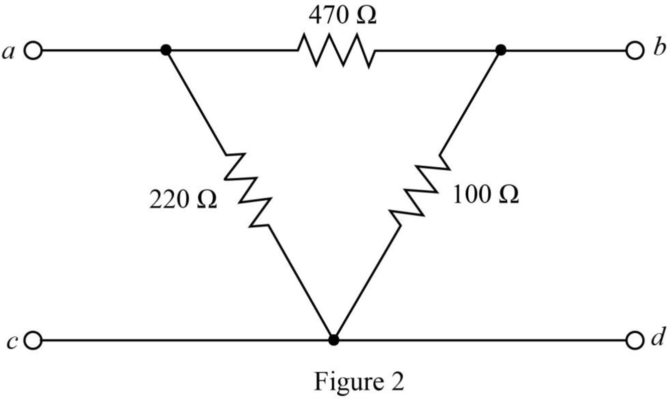
The given diagram is shown in Figure 1.
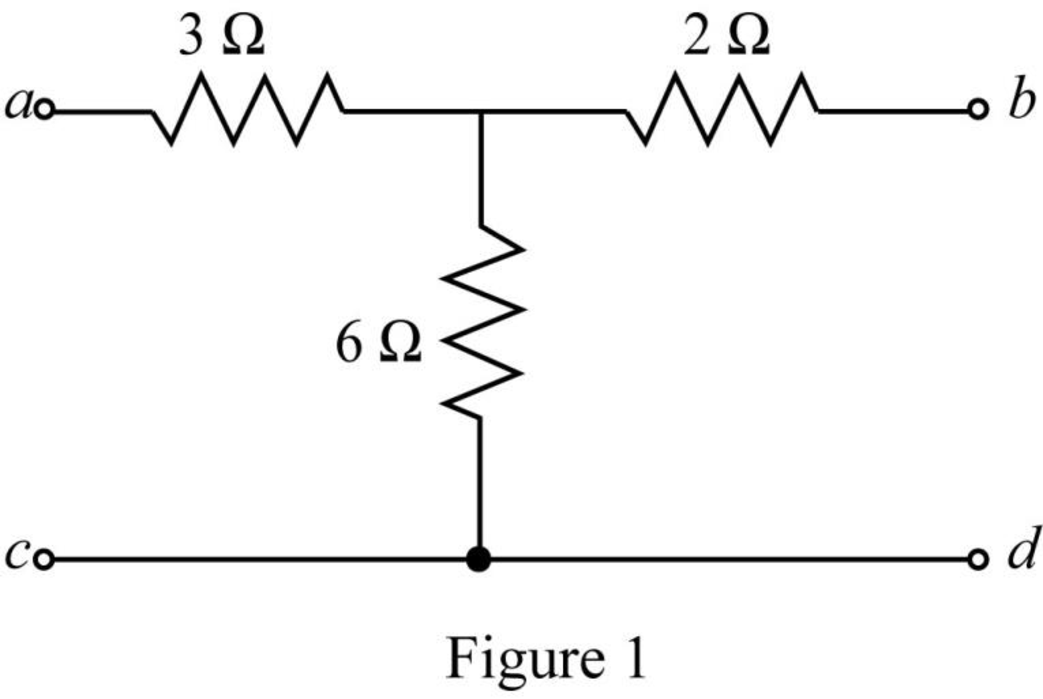
The given diagram is shown in Figure 2.
Calculation:
Determine the impedance parameter
The required diagram is shown in Figure 3.
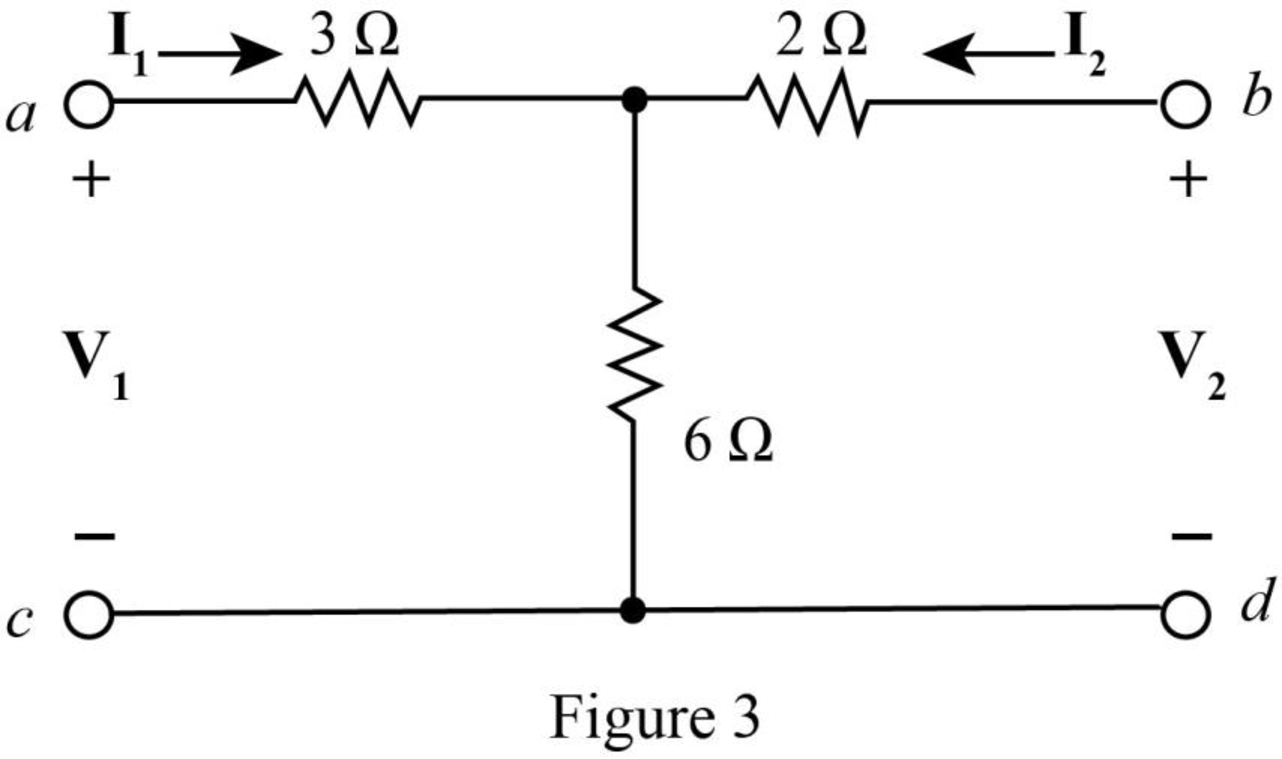
The impedance parameters can be expressed as,
Substitute
Substitute
Substitute
Substitute
Apply KVL left loop of Figure 3.
Substitute
Substitute
Substitute
Substitute
Apply KVL at the right loop.
Substitute
Substitute
Substitute
Substitute
Hence the
Convert the delta connected network to star connected network.
The required diagram is shown in Figure 4.
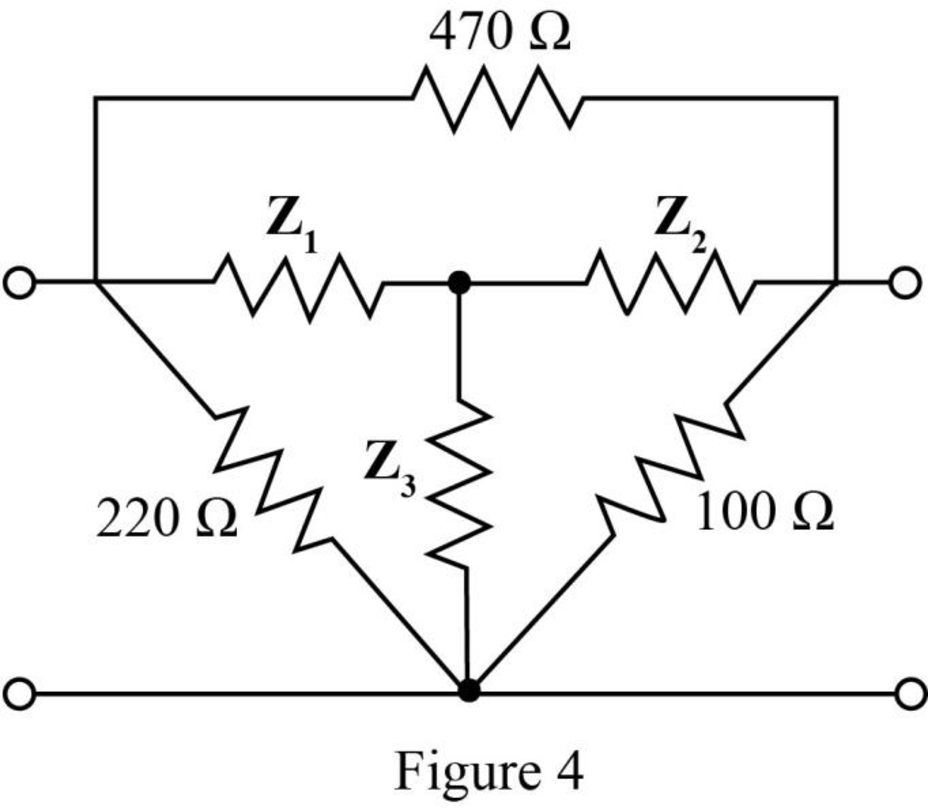
The impedance
The impedance
The impedance
Redraw the star connected circuit.
The required diagram is shown in Figure 5.
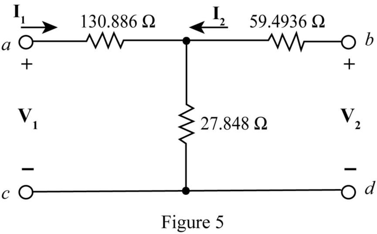
Apply KVL in the left loop.
Substitute
Substitute
Substitute
Substitute
Apply KVL at right loop of Figure 5.
Substitute
Substitute
Substitute
Substitute
The
The overall impedance matrix when the two port networks are connected in series is,
Substitute
Conclusion:
Therefore, the value of total impedance when the two port networks are connected in series is
(b)
The value of admittance parameters for the given condition.
Answer to Problem 35E
The value of total admittance when the two port networks are connected in parallel is
Explanation of Solution
Calculation:
The standard equation for admittance parameters is given by,
Substitute
Substitute
Substitute
Substitute
Modify the given diagram for
The required diagram is shown in Figure 6.
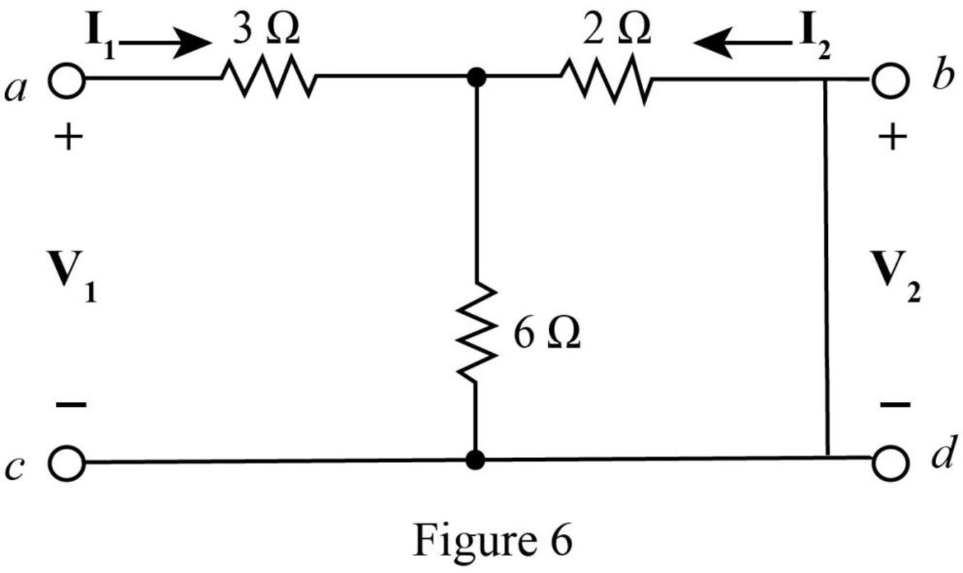
The resistances
The equivalent resistance is,
Further, the resistances
The total equivalent resistance of the circuit is given by,
Substitute
The input voltage calculated from the circuit is written as,
Rearrange the above equation as,
Substitute
Substitute
Rearrange equation (7) as,
Apply current division rule in Figure 6.
Substitute
Substitute
Modify the given diagram for
The required diagram is shown in Figure 7.
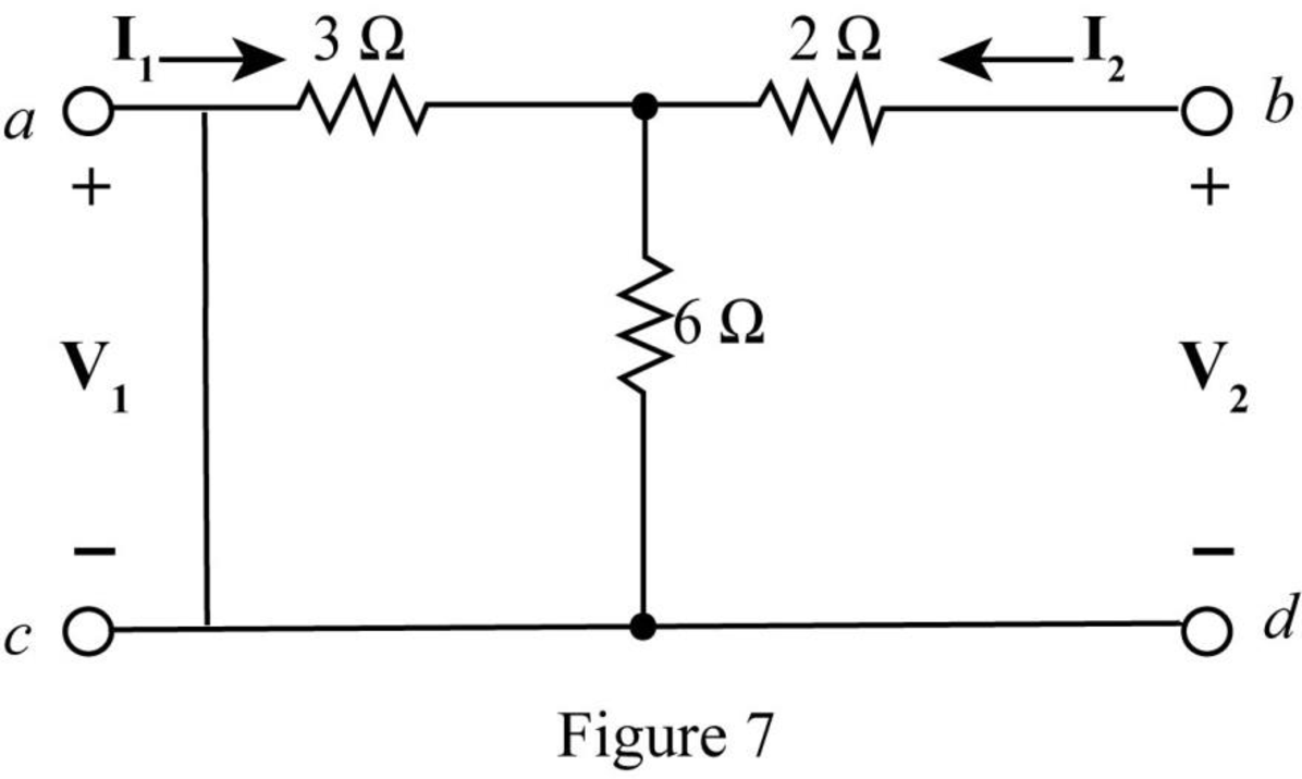
Rearrange equation (8).
Apply current division rule in the circuit of Figure 7.
Substitute
Substitute
The resistances
The equivalent resistance is,
Further, the resistances
The total equivalent resistance of the circuit is given by,
Substitute
The input voltage of Figure 7 can be expressed as,
Rearrange the above equation as,
Substitute
Substitute
The
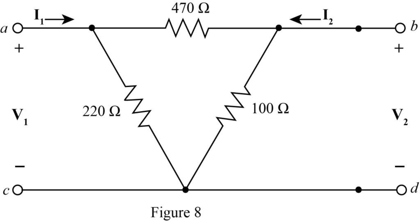
Redraw the Figure 2 and show the input voltage
The required diagram is shown in Figure 8.
Redraw the above figure for
The required diagram is shown in Figure 9.
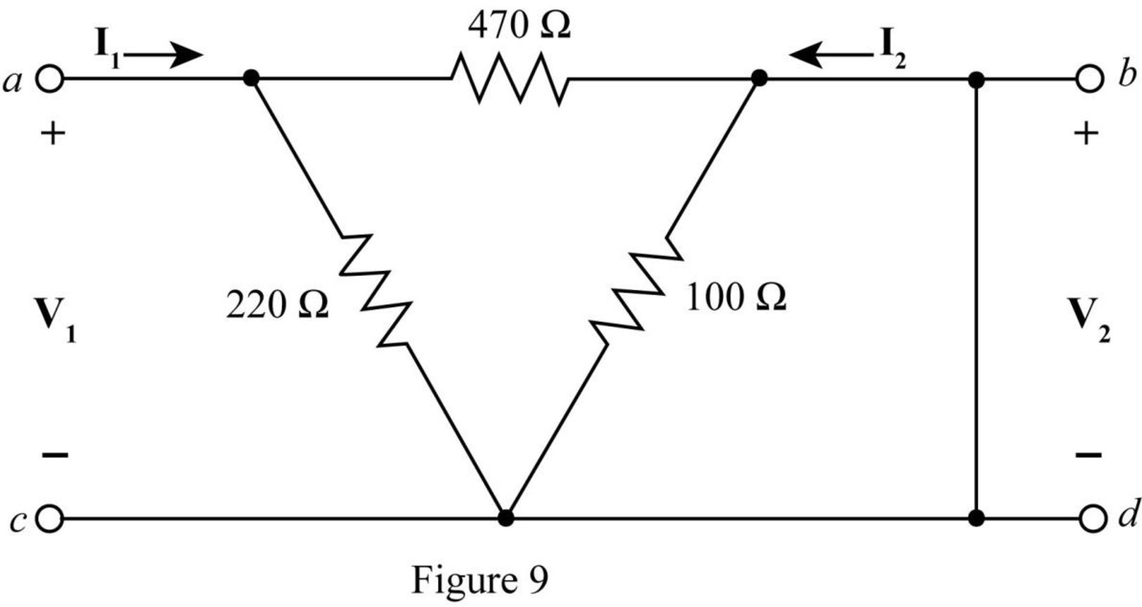
The
Therefore,
The equivalent resistance of the above circuit is,
The input voltage of Figure 9 can be expressed as,
Rearrange the above equation as,
Substitute
Substitute
The voltage across
Therefore, the current through
Rearrange the above equation as,
Substitute
Redraw the above figure for
The required diagram is shown in Figure 10.
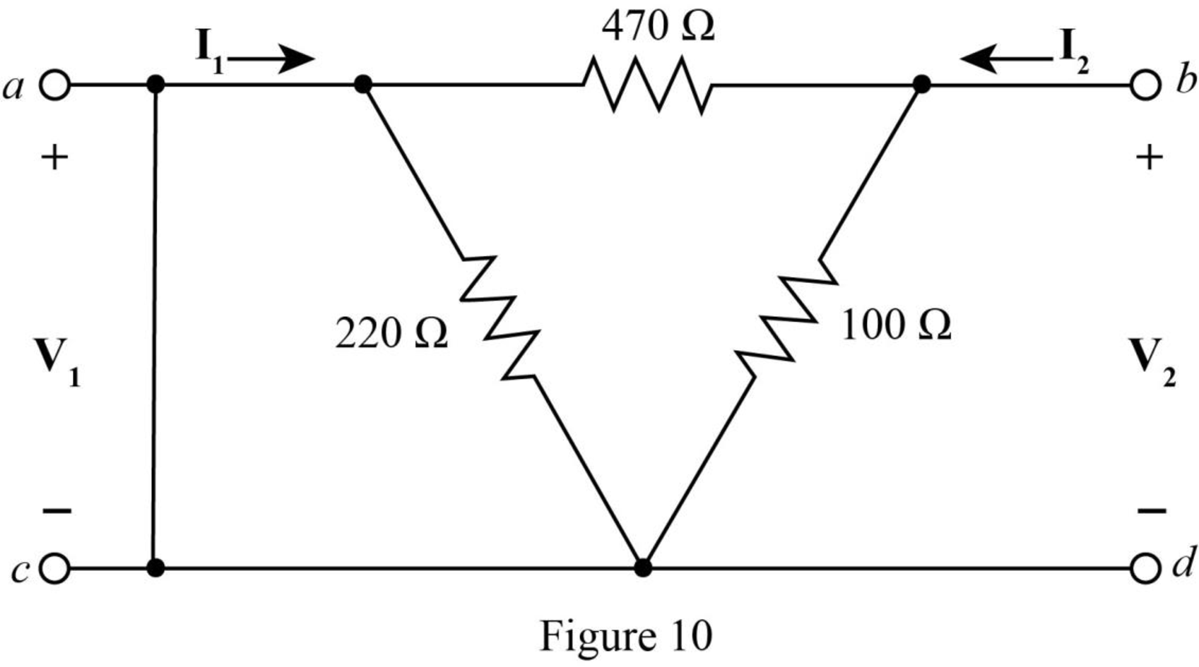
The
The voltage across
Therefore, the current through
Rearrange the above equation as,
Substitute
The
The equivalent resistance of the above circuit is,
The input voltage of Figure 10 can be expressed as,
Rearrange the above equation as,
Substitute
Substitute
The
The overall admittance matrix when the two port networks are connected in parallel is,
Substitute
Conclusion:
Therefore, the value of total admittance when the two port networks are connected in parallel is
(c)
The value of
Explanation of Solution
Calculation:
The determinant of
The matrix for
Substitute
The determinant of
Substitute
Conclusion:
Therefore, the value of
Want to see more full solutions like this?
Chapter 16 Solutions
Loose Leaf for Engineering Circuit Analysis Format: Loose-leaf
Additional Engineering Textbook Solutions
Electric Circuits. (11th Edition)
Principles and Applications of Electrical Engineering
Electric machinery fundamentals
Electrical Engineering: Principles & Applications (7th Edition)
ANALYSIS+DESIGN OF LINEAR CIRCUITS(LL)
Principles Of Electric Circuits


- If the Z parameter matrix of a two-port network is given by Z11 = 2- j4 Q Z12 = -j4 0 Z21 = j4 0 Z22 = -j2 0 The equivalent Y parameter matrix is given by Y11 =(real part) (imag part) S. Do not write units and j', round off to one(1) decimal place. Y12 = (real part) (imag part) S. Do not write units and 'j', round off to one(1) decimal place. Y21 =(real part) (imag part) S. Do not write units and 'j', round off to one(1) decimal place. Y22 =(real part) (imag part) S. Do not write units and 'j', round off to one(1) decimal place.arrow_forwardC. P = P, + USB + LSB eq 1 P = USB + LSB eq 2 After analyzing a modulation scheme, the above two results were obtained. As transmission engineer, you are to discuss the two expressions indicate which one will be preferred to the other and why your inclusion of the choice.arrow_forwardQ4. Use a Karnaugh map to minimize the following standard SOP expression: (15 M) ABC + ABC + ABC + ABC + ABC Q5. Plot the corresponding SUM and CARRY outputs of half-adder circuit, for the given A and B inputs. And give the logical expression for both. (15 M) HA A Barrow_forward
- Determine the Y-parameters at a frequency of 10 kHz for the two-port network shown in figure below. Present your answer in matrix form. R1 5 Ohm 1 Ohm 400 μF R3 4 Ohm R2 200 μF R5 L5 mom. 5 Ohm 796 µF 6.4 mHarrow_forwardExplain Adaptive XYZ Codec Using Mesh Architecture also write it's mathematical expression?arrow_forward4.Please solve a,b,c please be detailed in y-bus calculationsarrow_forward
- For a 4 - bus network, Zpus is shown below. r0.71660 0.60992 0.53340 0.58049] 0.60992 0.73190 0.64008 0.69659 0.53340 0.64008 0.71660 0.66951 Lo.58049 0.69659 0.66951 0.76310 Z Bus = j. When the refernce is changed from node (n) to node (1), Find: Z22 of the new impedance matrix Zausnew is: Select one: O a. 0.1832 O b. 0.22866 O c. 0.10688 O d. 0.13611 e. Nore of thesearrow_forwardJl äabiil (CME 446) 1 The Z matrix for the two-port network shown is j20 jo 3+ j2@ Then Z, in the circuit is jo on Za 1 O a. 3+j2w O b. None OC. 3+jw Od. jw O e. j2w f. 3 ENG ) G Aarrow_forwardIf the Z parameters for the Network bellow are: a- Find the output impedance Zout? b- Does the resistance at the output port absorb maximum power from the circuit? 50 IVarrow_forward
- Chegg Expert Hiring Signup X M Chegg Expert Hiring | Complete O Zoho Creator - Chegg Expert Hir X india.com/%23Form:Subject test?User_Name=3709413000271934727&Number%3D7 00 Maps Translate How do I create a u... D (5070) Creating and... B. How to download, i... Calculate the z- parameters for the following network: h,, = 50 2 h12 = 4 h21 =-8 I2 h22 =2 S Vị V2 h1 = 82 h12 = 2 h1 = -2 h22 =1S [57.66 2 3.33 2 (A) z = 3.33 2 0.66 2 39 2 1Ω (B) z = 6.66 2 3.33 [156 2 127arrow_forwardz Parameters 2.3 Given the two-port circuit below. VI V2 a) Find the z parameters. b) Is the circuit reciprocal? Why? c) Is the circuit symmetric? Why?arrow_forward1. (a) The Z-matrix of a 2-port network is given by [0.9 0.2] Z : 0.2 0.6] Find the Y-matrix of a given Z-matrix.arrow_forward
 Introductory Circuit Analysis (13th Edition)Electrical EngineeringISBN:9780133923605Author:Robert L. BoylestadPublisher:PEARSON
 Delmar's Standard Textbook Of ElectricityElectrical EngineeringISBN:9781337900348Author:Stephen L. HermanPublisher:Cengage Learning
 Programmable Logic ControllersElectrical EngineeringISBN:9780073373843Author:Frank D. PetruzellaPublisher:McGraw-Hill Education
 Fundamentals of Electric CircuitsElectrical EngineeringISBN:9780078028229Author:Charles K Alexander, Matthew SadikuPublisher:McGraw-Hill Education
 Electric Circuits. (11th Edition)Electrical EngineeringISBN:9780134746968Author:James W. Nilsson, Susan RiedelPublisher:PEARSON
 Engineering ElectromagneticsElectrical EngineeringISBN:9780078028151Author:Hayt, William H. (william Hart), Jr, BUCK, John A.Publisher:Mcgraw-hill Education,