
Videos
The required
Answer to Problem 39E
The required
Explanation of Solution
Given data:
The angular frequency is
Calculation:
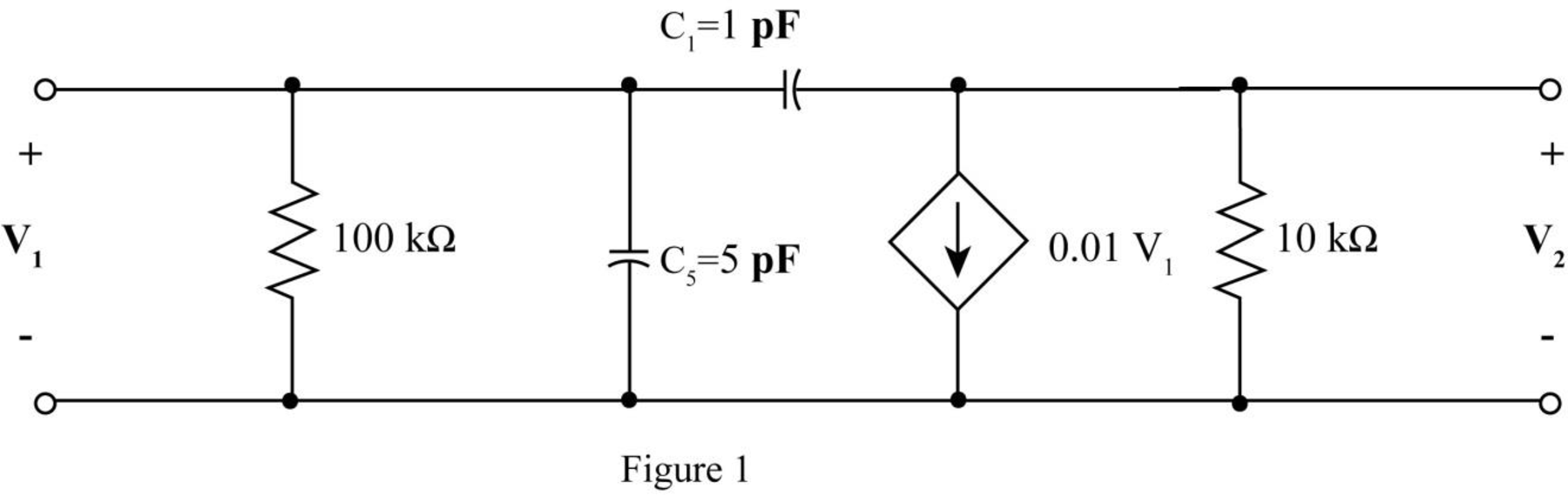
The given diagram is shown in Figure 1.
The conversion from
The conversion from
The conversion from
The conversion from
The conversion from
The capacitive reactance of
Substitute
The capacitive reactance of
Substitute
The modified diagram is shown in Figure 2.
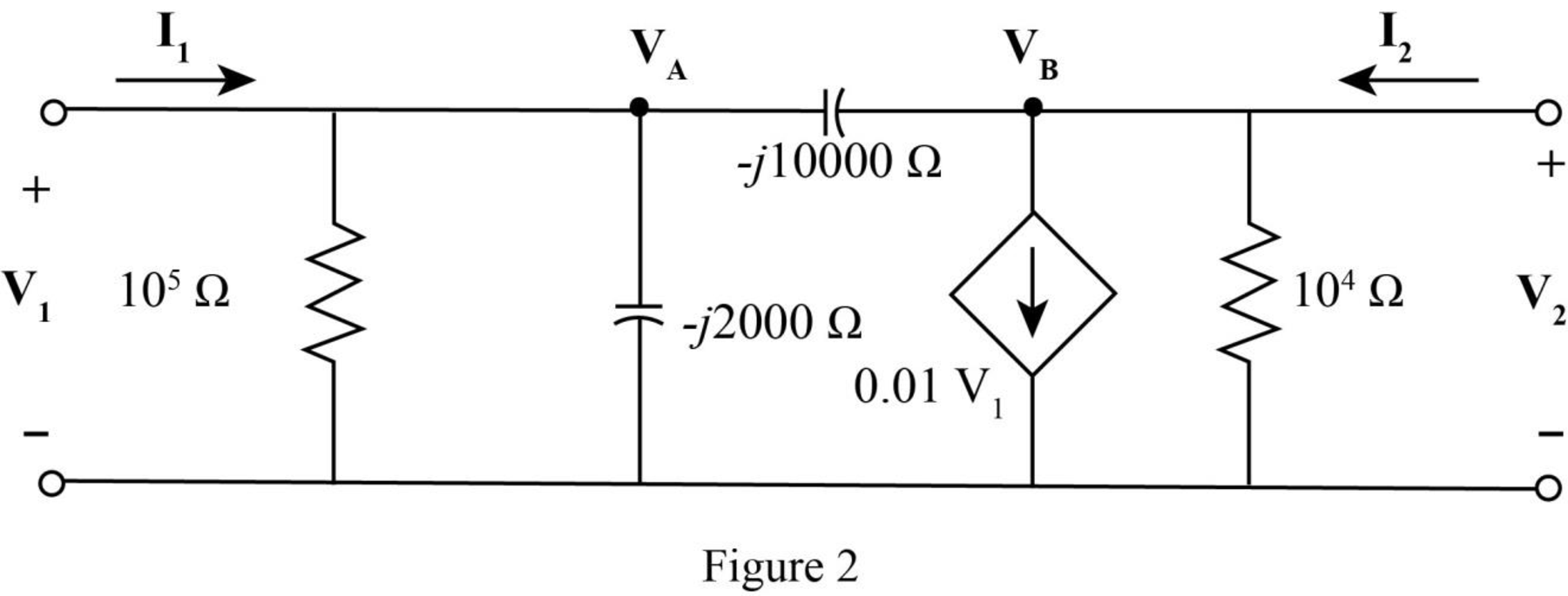
Apply KCL at node
Apply KCL at node
The standard equation for admittance parameters is,
Write equation (1) and equation (2) in matrix form.
Write equation (3) and equation (4) in matrix form
Compare equation (5) with equation (6).
The voltage expression
Substitute
The voltage expression
Substitute
The standard equation for impedance parameter are,
Compare equation (7) with equation (9).
Compare equation (8) with equation (10).
The
Conclusion:
Therefore, the required
Want to see more full solutions like this?
Chapter 16 Solutions
Loose Leaf for Engineering Circuit Analysis Format: Loose-leaf


- Provide the transfer function of the systemarrow_forward16. The resistor value of Norton equivalent, RN, for the circuit in Fig. 15, is 102 ww 20 2 0.5%, (a) 62 (b) 5.22 (c) 4.12 (d) 3.332arrow_forwardConsider the digital circuit shown below - B. Y D Compute the value of Y if A=1, B=1, and C=1,arrow_forward
- 16.9 a. Design a hard limiter as shown in Fig. 16.15(a) by determining the values of R₁, R2, R3, R4, and R5. The circuit should limit the negative output voltage to Vo(min) = -7 V and the positive voltage to Vo(max) = 9 V. The magnitude of the slopes after the break points should be less than or equal to 1 50. The diode drop is vp = 0.7 V at ip = 0.1 mA. The DC supplies are given by VA-VB = 15 V. P b. Use PSpice/SPICE to plot the transfer characteristic. Assume Vcc= 15 V, -VEE = -15 V, and vs = -5 V to 5 V. Use the PSpice/SPICE op-amp macromodel. R₂=R₁ Vref=0V= +Vcc -VEE D₂ R₂ R₂ Rs For Probs. 16.10 through 16.14, use comparator LM111 and vs = 10 sin (2000) to plot the hysteresis characteristic using PSpice/SPICE.arrow_forward16.14 Design a noninverting Schmitt trigger with the reference voltage of Fig. 16.29(a) so that VHt = 8 V and VLt = 4 V. Assume Vsat = |- Vsat | = 12 V. P Vref ię RF D Vd A Rx R₁arrow_forwardUsing the Block diagram reduction technique find the Transfer Function of the systemarrow_forward
- ona) V B, VGb) V EC) IE, IC and IDD) IBE) VC, VS and VDF) VCE, VDSfind their value(x.xk= 1.8 k)arrow_forwardFor the cascaded amplifier shown below, determine the output voltage V.. Show the details of your work. Write your solution on a white typewriting paper, scan it in JPEG format and upioad it to the space provided below. 3.6 kn 36 kl 15 mV. 15V 10 kn 13 kn 30 πV 15V 1.3 kn 1.3 kn 15V 10 mV 13 kn 15V -15Varrow_forward1. In a two-port network, the output short-circuit current was measured while the source voltage at the input was IV; the valuc of the output current would provide thc parameter a) y2ı c) yı2 b) h21 d) z12 2. For a constant gain k, log-magnitude curve in Bode plot is a) negative c) zero b) positive d) depending upon the value of k 3. A transformer is said to be ideal if it has a) coils are lossless c) coils have very large reactances b) unity-coupled d) all previously mentionedarrow_forward
- Q4: Determine the minimum transmission bandwidth required to transmit the following two signals: f1(t) = 10 cos 150 nt + 15 cos 200 t and f2(t) = 10 cos 100 t cos 200 t in a PAM/TDM system. Compare the result if FDM is used with AM & SSB techniques. Ans: 300HZ.arrow_forwardDetermine the transfer function of systems shown in the diagrams belowarrow_forwardFind the transfer function G(s) = VL(s)/V (s) for each networks. Solve each problems using Mesh Analysis. Define your variables clearly and show all the necessary solutions.arrow_forward
 Introductory Circuit Analysis (13th Edition)Electrical EngineeringISBN:9780133923605Author:Robert L. BoylestadPublisher:PEARSON
 Delmar's Standard Textbook Of ElectricityElectrical EngineeringISBN:9781337900348Author:Stephen L. HermanPublisher:Cengage Learning
 Programmable Logic ControllersElectrical EngineeringISBN:9780073373843Author:Frank D. PetruzellaPublisher:McGraw-Hill Education
 Fundamentals of Electric CircuitsElectrical EngineeringISBN:9780078028229Author:Charles K Alexander, Matthew SadikuPublisher:McGraw-Hill Education
 Electric Circuits. (11th Edition)Electrical EngineeringISBN:9780134746968Author:James W. Nilsson, Susan RiedelPublisher:PEARSON
 Engineering ElectromagneticsElectrical EngineeringISBN:9780078028151Author:Hayt, William H. (william Hart), Jr, BUCK, John A.Publisher:Mcgraw-hill Education,