
Videos
Referring to the circuit depicted in Fig. 3.45, count the number of (a) nodes;
(b) elements; (c) branches.
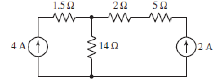
FIGURE 3.45
(a)
Find the number of nodes in the circuit.
Answer to Problem 1E
Number of nodes in the circuit is
Explanation of Solution
The circuit diagram is redrawn as shown in Figure 1.
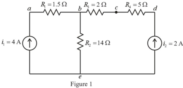
Refer to the redrawn Figure 1.
A point where two or more branches have common connection is known as node.
In Figure 1 two branches are connected at point
Conclusion:
Thus, the number of nodes in the circuit is
(b)
Find the number of elements in the circuit.
Answer to Problem 1E
Number of elements in the circuit is
Explanation of Solution
Refer to the redrawn Figure 1.
Each component (either passive or active device) present in the electrical circuit is an element.
There are
Conclusion:
Thus, the number of elements in the circuit is
(c)
Find the number of branches in the circuit.
Answer to Problem 1E
Number of branches in the circuit is
Explanation of Solution
Refer to the redrawn Figure 1.
Each electrical element or device present in the circuit is known as branch.
There are
Conclusion:
Thus, the number of branches in the circuit is
Want to see more full solutions like this?
Chapter 3 Solutions
Loose Leaf for Engineering Circuit Analysis Format: Loose-leaf


- Determine a valuc for the voltage vas labeled in the circuit of Fig 3.70, and compute the power supplied by the two current sources -2A 100ZR, 3A( R:arrow_forward3.15. Plot the V out as a function of Vx in the cir- cuit of Fig. 3.72. Assume Vx = Vo sin wt and a constant-voltage diode model. + Vx R Vout VB Figure 3.72arrow_forwardAn independent voltage source is characterized by a terminal voltage which Select one: a. is completely independent of the current through it. b. None of the above C. is completely dependent on the current through it. d. is completely independent of the power dissipated by it. OO Shot by Hisense H12arrow_forward
- Subject: Circuits IShow your solutions pleasearrow_forwardD,on B2. 3.40. We wish to design a circuit that exhibits the input/output characteristic shown in Fig. 3.83. Using 1-k2 resistors, ideal diodes, and other components, construct the circuit. Vout + 2 V 0.5 -2 V + 2 V Vin -2 V 0.5 Figure 3.83arrow_forward7. With the help of circuit diagram (Fig3) given below draw the output voltage and current waveform D₂ S Figure 3: circuit diagram KH D₂arrow_forward
- What value of Is in the circuit of Fig. 3.78 will result in a zero voltage v? 1.28 A Is -2.57 A IFIGURE 3.78arrow_forwardNumber: 3.56 Determine correctly V1 and V2 in the circuit of Figure 3.101arrow_forwardmponent of nódal ch element. There is no way of knowing the current through wever, KCL must be satisfied at a sunernode like any other node. Hence a tde spernode in Fig. 3.5, i + i4 = i2 + i3 (3.11a) v1 - v2 v1 - v3 v2 – 0 v3 - 0 (3.11b) 6. To apply Kirchhoff's voltage law to the supernode in Fig. 3.4 we redraw the circuit as shown in Fig. 3.5. Going around the loop in the clockwise»direction gives -V2 + 5 + v3 = 0=v2 – V3 = 5 (3.12) From Eqs. (3.10), (3.11b), and (3.12), we obtain the node volltages. 5V د مُسق ک من ؤ Figure 3.5 Applying KVL to a supernode. Example 3.2: For the circuit shown in Fig. 3.6, find the node voltages. Solution: The supernode contains the 2-V source, nodes 1 and 10 2 www 2, and the 10-2 resistor. Applying KCL to the 2 V supernode as shown in Fig. 3.7(a) gives 2. 12 2 = i + iz +7 7 A Expressing in and iz in terms of the node voltages 2 A 22 v1 - 0 v2 - 0 2 = 7 4 or (3.2.1) V2 =-20 - 2vVI Figure 3.6 For Example 3.2. ESTHRER: ALI SHARAAN METHORS OF ANALYSIS…arrow_forward
 Introductory Circuit Analysis (13th Edition)Electrical EngineeringISBN:9780133923605Author:Robert L. BoylestadPublisher:PEARSON
 Delmar's Standard Textbook Of ElectricityElectrical EngineeringISBN:9781337900348Author:Stephen L. HermanPublisher:Cengage Learning
 Programmable Logic ControllersElectrical EngineeringISBN:9780073373843Author:Frank D. PetruzellaPublisher:McGraw-Hill Education
 Fundamentals of Electric CircuitsElectrical EngineeringISBN:9780078028229Author:Charles K Alexander, Matthew SadikuPublisher:McGraw-Hill Education
 Electric Circuits. (11th Edition)Electrical EngineeringISBN:9780134746968Author:James W. Nilsson, Susan RiedelPublisher:PEARSON
 Engineering ElectromagneticsElectrical EngineeringISBN:9780078028151Author:Hayt, William H. (william Hart), Jr, BUCK, John A.Publisher:Mcgraw-hill Education,