
Concept explainers
Videos
Compute the power absorbed by each element in the circuit of Fig. 3.68 if the mysterious element X is (a) a 13 Ω resistor; (b) a dependent voltage source labeled 4v1, “+” reference on top; (c) a dependent voltage source labeled 4ix, “+” reference on top.
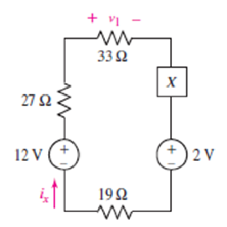
FIGURE 3.68
(a)
Find the power absorbed by each element.
Answer to Problem 28E
Power absorbed by
Explanation of Solution
Given Data:
Element
Formula used:
The expression for power absorbed by voltage source is as follows.
Here,
The expression for power absorbed by resistor is as follows.
Here,
Calculation:
The circuit diagram is redrawn as shown in Figure 1.
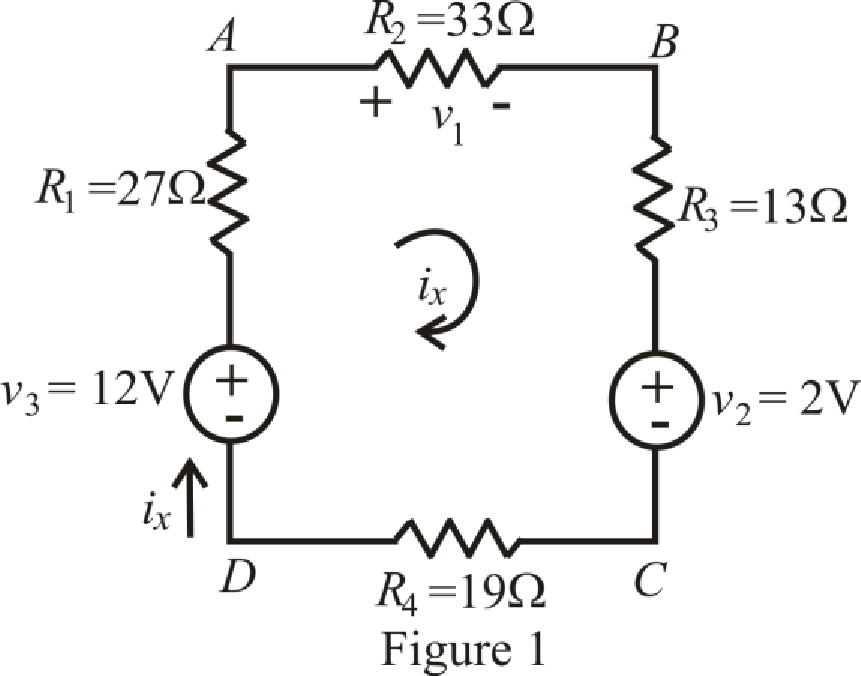
Refer to the redrawn Figure 1.
The expression for KVL in mesh
Here,
Substitute
Rearrange equation (4) for
Current is leaving the positive terminal and we are calculating power absorbed hence current should leave by negative terminal so we will use magnitude of voltage with negative sign, therefore, value of
Substitute
So power absorbed by independent voltage source
Substitute
So, the power absorbed by resistor
Substitute
So power absorbed by resistor
Substitute
So power absorbed by resistor
Substitute
So power absorbed by independent voltage source
Substitute
So power absorbed by resistor
Conclusion:
Thus, power absorbed by
(b)
Find power absorbed by each element.
Answer to Problem 28E
Power absorbed by
Explanation of Solution
Given Data:
Element
Calculation:
The circuit diagram is redrawn as shown in Figure 2,
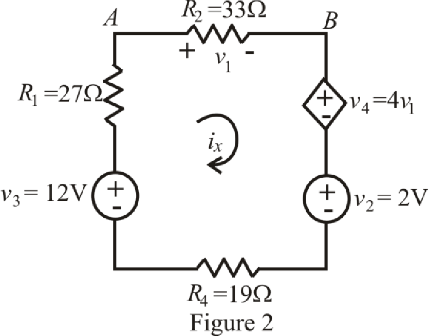
Refer to the redrawn Figure 2,
The expression for KVL in mesh
Here,
The expression for voltage
Here,
The expression for voltage
Here,
Refer to the redrawn Figure 2,
Substitute
Substitute
Rearrange equation (9) for
Current is leaving the positive terminal and we are calculating power absorbed hence current should leave by negative terminal so we will use magnitude of voltage with negative sign, therefore, value of
Substitute
So power absorbed by independent voltage source
Substitute
So power absorbed by resistor
Substitute
So power absorbed by resistor
Substitute
Substitute
Substitute
So power absorbed by dependent voltage source
Substitute
So power absorbed by independent voltage source
Substitute
So power absorbed by resistor
Conclusion:
Thus, power absorbed by
(c)
Find power absorbed by each element.
Answer to Problem 28E
Power absorbed by
Explanation of Solution
Given Data:
Element
Calculation:
The circuit diagram is redrawn as shown in Figure 3.
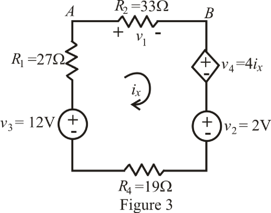
Refer to the redrawn Figure 3,
The expression for KVL in mesh
Here,
The expression for voltage
Here,
Refer to the redrawn Figure 2,
Substitute
Rearrange equation (12) for
Current is leaving the positive terminal and we are calculating power absorbed hence current should leave by negative terminal so we will use magnitude of voltage with negative sign, therefore, value of
Substitute
So power absorbed by independent voltage source
Substitute
So power absorbed by resistor
Substitute
So power absorbed by resistor
Substitute
Substitute
So power absorbed by dependent voltage source
Substitute
So power absorbed by independent voltage source
Substitute
So power absorbed by resistor
Conclusion:
Thus, power absorbed by
Want to see more full solutions like this?
Chapter 3 Solutions
Loose Leaf for Engineering Circuit Analysis Format: Loose-leaf


- 1. Determine the following: (a) .o be Total Current and Total LEC Power of the circuit; (b) the VA = 120 V current passing through each resistors; (c) The voltage drop across each resistors; (d) the power taken by each resistor. R = 30 2 . MERVAN P, DE MOHAMMEI I = ? R3 = 50 2 So oti 13 =? st given to the earer, for this work to be presented or R, = 40 2 LECTURE SLIDE O MEVIN ,OHAJAME SLIDE ON I PEMOHAMM R4 = 60 2 14 = ? ork to be presented or shown to others. + Rs = 60 2 shown to ohers. er, for this work to be pre Cthers. rthis work to be presented or shown R = 70 2 I6 = ? co the hown to others. 1, = ? TURE SLIDES MOHAMN R, = 80 2 CONSENT wasot given to the bearer, for this work to farrow_forward7. If a third resistor (R3), identical to the other two, is added in parallel with the first two, then the electric potential difference (voltage drop) across each of the three individual resistors will a. increase. b. decrease c. remain the same 8. Which of the following statements is true about resistance? (State True or False AND EXPLAIN YOUR REASON AND SHOW CALCULATIONS).arrow_forwardQ3// i) Find the total energy stored in the circuit of Figure 3. 2H 3 H 12 V 6 A 2F Figure 3arrow_forward
- Q3: Calculate the voltage of 252 resistance in the following circuit. 300 100 (30v 300 250 www MAM www-arrow_forward66% @ P 2:00 A docs.google.com ll. Classroom Q1/ Solve as required below. * Find I, L,Is, In, Îs & Power at (lov) Source 24 lov 1 Add file Q2/ Solve as required below. * use Voltage divider rule to fined Vi &, tosr 3ov 1 Add filearrow_forward1. Two identical batteries are available. If the batteries are connected in series and a voltmeter is used to measure its terminal voltage, the voltmeter reads 18 V. If the batteries are connected in series to supply power to load R, R receives 6 A. If the batteries are connected in parallel to supply power to the same load R, R receives 10/3 A Find the Emf (E) and internal resistance (r) of each battery and the value of R.arrow_forward
- A 230-V, 1 000-c/s voltage is applied to a resistor in series with C capacıtance 0 06 µF, the reading is 100 V. Find the current when the voltmeter is disconnected. 86 0 05 µF. When C is shunted by a voltmeter of [0 0527 A.]arrow_forward2. A single range ammeter is to be extended as multi-range ammeter by adding shunt resistors as given. Calculate the ohmic values of R1, R2 and R3 for the meter to measure a current of 1A, 10A and 100A respectively. R3 www Rm = 50 ohms 10 A IFSD = 1 μA R2 ww R1 100 Aarrow_forward3. Draw clearly the circuits given in Figure 3 (a and b) on the paper provided for your use in the LMS. Rs R, R2 R4 R3 E, R Ra Rs V (t (a) (b) Figure 3arrow_forward
- In the circuit shown in the figure below, C1=39µF, C2=25µF, C3=22µF, and a voltage Vab=48V is applied accross points a and b. After C1 is fully charged, the switch is thrown to the right. What is the final voltage on C2? Express your answer in units of V(Volts) using one decimal place. C2 C1T C3 b HAEarrow_forwardQuestion 11 Given the below circuit, answer the following: 6V A). C) B). A Law i¹ R1 40 B www i2=0.31A R2 30Ω R3 2002 13=0.465A [PI1b] [PI1c] Find the value of il and the voltage VBA. [PI1c] Find the power of the 6V source and state whether it is supplied or absorbed. [PI1c] Use KVL to find the voltage VBC and verify it using Ohm's 11.6Aarrow_forwardQUESTION 3 A voltmeter, having a sensitivity of 1,000 $2/V, reads 100V on its 150V scale when connected across an unknown resistor, Rx in series with a milli-ammeter as shown in Figure Q3. Calculate the actual resistance of the unknown resistor, Rx in k2 when the milli-ammeter reads 5mA. A mili-ammeter B X R, ΚΩ Y v voltmeter Figure Q3arrow_forward
 Introductory Circuit Analysis (13th Edition)Electrical EngineeringISBN:9780133923605Author:Robert L. BoylestadPublisher:PEARSON
 Delmar's Standard Textbook Of ElectricityElectrical EngineeringISBN:9781337900348Author:Stephen L. HermanPublisher:Cengage Learning
 Programmable Logic ControllersElectrical EngineeringISBN:9780073373843Author:Frank D. PetruzellaPublisher:McGraw-Hill Education
 Fundamentals of Electric CircuitsElectrical EngineeringISBN:9780078028229Author:Charles K Alexander, Matthew SadikuPublisher:McGraw-Hill Education
 Electric Circuits. (11th Edition)Electrical EngineeringISBN:9780134746968Author:James W. Nilsson, Susan RiedelPublisher:PEARSON
 Engineering ElectromagneticsElectrical EngineeringISBN:9780078028151Author:Hayt, William H. (william Hart), Jr, BUCK, John A.Publisher:Mcgraw-hill Education,