
Videos
Consider the seven-element circuit depicted in Fig. 3.99. (a) How many nodes, loops, and branches does it contain? (b) Calculate the current flowing through each resistor. (c) Determine the voltage across the current source, assuming the top terminal is the positive reference terminal.
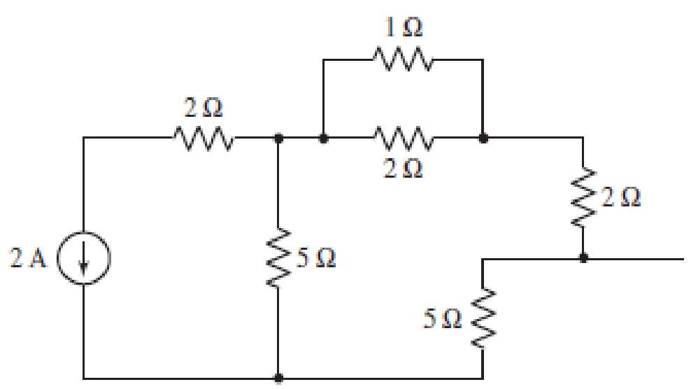
■ FIGURE 3.99
(a)
Find the number of nodes, number of loops and number of branches in the circuit.
Answer to Problem 63E
Number of nodes in the circuit is
Explanation of Solution
The circuit diagram is redrawn as shown in Figure 1.
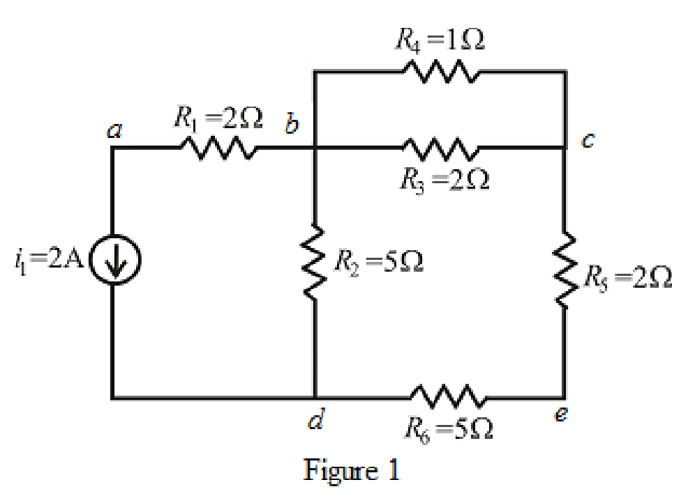
Refer to the redrawn Figure 1.
A point where two or more branches have common connection is known as node.
In Figure 1 two branches are connected at point
Each electrical element or device present in the circuit is known as branch.
There is
The circuit diagram is redrawn as shown in Figure 2,
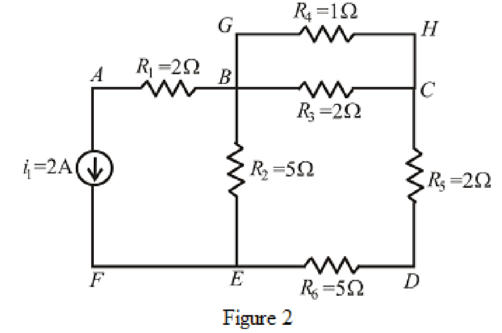
Refer to the redrawn Figure 2,
If starting and ending node is same for a path then it is known as closed path or loop.
Conclusion:
Thus, the number of nodes in the circuit is
(b)
Find the value of current through each resistor.
Answer to Problem 63E
The value of current through
Explanation of Solution
Formula used:
The expression for parallel combination of resistance is as follows.
Here,
Calculation:
The circuit diagram is redrawn as shown in Figure 3.
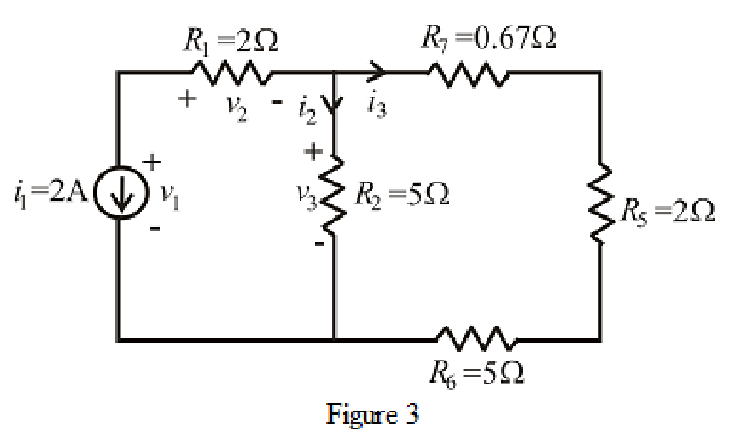
Refer to the redrawn Figure 3.
The expression for current
Here,
The expression for current
Here,
Refer to the redrawn Figure 1.
The expression for current
Here,
The expression for current
Here,
Refer to the redrawn Figure 1.
As
Rearrange for
Refer to the redrawn Figure 3.
As current source direction is downward means change sign of current means value of current is
Substitute
As resistor
So value of current through resistor
Substitute
So, the value of current through resistor
Refer to the redrawn Figure 1.
Substitute
So, the value of current through resistor
Substitute
So, the value of current through resistor
As resistor
Conclusion:
Thus, the value of current through
(c)
Find value of voltage across current source.
Answer to Problem 63E
The voltage across current source is
Explanation of Solution
Formula used:
The expression for voltage is as follows.
Here,
Calculation:
Refer to the redrawn Figure 3.
The expression for voltage
Here,
Refer to the redrawn Figure 3.
Substitute
So value of voltage
Substitute
So value of voltage
Substitute
Conclusion:
Thus, the voltage across current source is
Want to see more full solutions like this?
Chapter 3 Solutions
Loose Leaf for Engineering Circuit Analysis Format: Loose-leaf


- Dr. Yaseen H. Tahir Example: a) Convert the current souree of Figure below to an equivalent voltage source. 6) Prove your answer. (Home work) 1. 5 mA 10K2 20K2arrow_forwardShow all steps and solution. Electrical engineeringarrow_forwardA sensitive ammeter (micro-ammeter) is used to manufacture an analog DC voltmeter. The ammeter has the characteristics: 100µA full-scale indication, internal resistance Ri=200ohm. Voltmeter Rs V R = Ri HA Measured_Voltage Calculate the series resistor Rs to obtain a voltmeter able to measure 50V (full scale). 5.9kohm 6kohm 119.9kohm 120kohm 199.5kohm 200kohm 499.8kohm 500kohm (hparrow_forward
- Calculate the equivalent voltage in the given below: (Type the numerical value only) B1 = 6.49 V; B2 = 10.52 V; B3 = 9.16 V; B4 = 13.45 V DC SOURCES IN SERIES NUMBER 1 [B1] V HANDEPREL [B2] V OFF [B3] V Equivalent Voltage: OFF 0. CE [B4] V Round your answer to 2 decimal places.arrow_forward21, R2 Va k V3 R1 2A 4V Ve For the above circuit, with R = 7Ohms and R,= 2 0hms, use nodal analysis to determine the voltage at the node V, in Volts. Round your answer to the nearest single digit decimal place. For example, if you calculate 3.27 Volts, then enter 3.3 as your answer. Moving to another question will save this response. o|自 2Type here to searcharrow_forwarda) Using the circuit schematic, find a set of three equations that will allow you to solve for the three currents. b) What are the currents if Ԑ1=28 V, Ԑ2=9 V, R1=177 Ω, R2=293 Ω, R3=326 Ω, and R4=104 Ω. ? To continue, please enter the result of I3 in units of A. Round your answer to 3 decimal placesarrow_forward
- A 213-V battery, an inductor, and a resistor are connected in series as shown in the diagram below. A two-way switch makes it possible to include or exclude the battery. The switch that had been in position 1 for a long time is suddenly moved to position 2. (Enter your answers to at least two decimal places.) ll ll AV AV O 2 1 (i) (ii) (a) What is the voltage across the resistor at the end of five time constants? V (b) At this time, what is the voltage across the inductor? Varrow_forwarda) For the circuit shown in Figure (3.a), find i, using any method. 9kQ 12kn 12k0 6kn 12v 6y i, Figure 3.aarrow_forwardQ3) A) Find RAB for the circuit shown in Figure 3. A O 4 N 50 Figure 3arrow_forward
- If “A”V=28,“B” V“=25,A1”A=47,“A2”A=931/The expected value of the voltage across a resistor is ‘A’V. However, measurement yields a value of‘B’ V. Calculate: a)Absolute error b) Percentage error c) Absolute accuracy d) Relative accuracy 2/A (0 – 100) A range ammeter has inaccuracy of ± .04% of its full scale. Calculate the % error ininstrument if the expected value is (i) ‘A1’Aand (ii) ‘A2’A.arrow_forwardSubject:Circuitsshow your solutions pleasearrow_forwardSubject: CircuitsShow your solutions pleasearrow_forward
 Introductory Circuit Analysis (13th Edition)Electrical EngineeringISBN:9780133923605Author:Robert L. BoylestadPublisher:PEARSON
 Delmar's Standard Textbook Of ElectricityElectrical EngineeringISBN:9781337900348Author:Stephen L. HermanPublisher:Cengage Learning
 Programmable Logic ControllersElectrical EngineeringISBN:9780073373843Author:Frank D. PetruzellaPublisher:McGraw-Hill Education
 Fundamentals of Electric CircuitsElectrical EngineeringISBN:9780078028229Author:Charles K Alexander, Matthew SadikuPublisher:McGraw-Hill Education
 Electric Circuits. (11th Edition)Electrical EngineeringISBN:9780134746968Author:James W. Nilsson, Susan RiedelPublisher:PEARSON
 Engineering ElectromagneticsElectrical EngineeringISBN:9780078028151Author:Hayt, William H. (william Hart), Jr, BUCK, John A.Publisher:Mcgraw-hill Education,