
Loose Leaf for Engineering Circuit Analysis Format: Loose-leaf
9th Edition
ISBN: 9781259989452
Author: Hayt
Publisher: Mcgraw Hill Publishers
expand_more
expand_more
format_list_bulleted
Concept explainers
Videos
Textbook Question
Chapter 3.2, Problem 1P
3.1 (a) Count the number of branches and nodes in the circuit in Fig. 3.4. (b) If ix = 3 A and the 18 V source delivers 8 A of current, what is the value of RA? (Hint: You need Ohm’s law as well as KCL.)
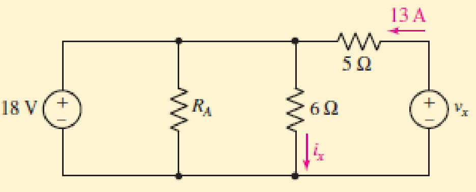
FIGURE 3.4
Expert Solution & Answer
Want to see the full answer?
Check out a sample textbook solution
Students have asked these similar questions
Example: Find current i, and voltage in the circuit shown below using KCL
osi
3A
1. A galvanometer is to be used as a multi-range dc voltmeter. If the full scale current deflection is
100μA and the galvanometer internal resistance is 2k2, calculate the ohmic value or R1, R2 and R3 for
the meter to be extended as 10V, 100V and 750V voltmeter.
750V
R3
100V
R2
ww
R1
10V
IFSD = 100μA
Rm = 2000 ohms
Suppose a 10.0 ohm resistor is connected to an emf source to make a closed circuit. If the source has emf
= 15.0 V with an internal resistance r = 0.5 ohms, which of the following correctly compares the voltage
drop across the emf source and the attached resistor?
O a. Voltage drop across emf source is directly proportional to the external resistor
O b. Voltage drop across emf source is greater than external resistor
O c. Voltage drop across emf source is less than external resistor
O d. Voltage drop is the same for the emf source and the external resistor
O e. None of the above
Chapter 3 Solutions
Loose Leaf for Engineering Circuit Analysis Format: Loose-leaf
Ch. 3.2 - 3.1 (a) Count the number of branches and nodes in...Ch. 3.3 - Determine ix and vx in the circuit of Fig. 3.7....Ch. 3.3 - For the circuit of Fig. 3.9, if vR1=1V, determine...Ch. 3.3 - Determine vx in the circuit of Fig. 3.11.Ch. 3.4 - In the circuit of Fig. 3.12b, vs1 = 120 V, vs2 =...Ch. 3.4 - 3.6 In the circuit of Fig. 3.14, find the power...Ch. 3.5 - Determine v in the circuit of Fig. 3.16.Ch. 3.5 - For the single-node-pair circuit of Fig. 3.18,...Ch. 3.6 - Determine the current i in the circuit of Fig....Ch. 3.6 - Determine the voltage v in the circuit of Fig....
Ch. 3.6 - Determine whether the circuit of Fig. 3.25...Ch. 3.7 - 3.12 Determine a single-value equivalent...Ch. 3.7 - 3.13 Determine i in the circuit of Fig. 3.29....Ch. 3.7 - Determine v in the circuit of Fig. 3.31 by first...Ch. 3.7 - 3.15 For the circuit of Fig. 3.33, calculate the...Ch. 3.8 - 3.16 Use voltage division to determine vx in the...Ch. 3.8 - In the circuit of Fig. 3.40, use resistance...Ch. 3 - Referring to the circuit depicted in Fig. 3.45,...Ch. 3 - Referring to the circuit depicted in Fig. 3.46,...Ch. 3 - For the circuit of Fig. 3.47: (a) Count the number...Ch. 3 - For the circuit of Fig. 3.47: (a) Count the number...Ch. 3 - Refer to the circuit of Fig. 3.48, and answer the...Ch. 3 - A local restaurant has a neon sign constructed...Ch. 3 - Referring to the single-node diagram of Fig. 3.50,...Ch. 3 - Determine the current labeled I in each of the...Ch. 3 - In the circuit shown in Fig. 3.52, the resistor...Ch. 3 - The circuit of Fig. 3.53 represents a system...Ch. 3 - In the circuit depicted in Fig. 3.54, ix is...Ch. 3 - For the circuit of Fig. 3.55 (which employs a...Ch. 3 - Determine the current labeled I3 in the circuit of...Ch. 3 - Study the circuit depicted in Fig. 3.57, and...Ch. 3 - Prob. 15ECh. 3 - For the circuit of Fig. 3.58: (a) Determine the...Ch. 3 - For each of the circuits in Fig. 3.59, determine...Ch. 3 - Use KVL to obtain a numerical value for the...Ch. 3 - Prob. 19ECh. 3 - In the circuit of Fig. 3.55, calculate the voltage...Ch. 3 - Determine the value of vx as labeled in the...Ch. 3 - Consider the simple circuit shown in Fig. 3.63....Ch. 3 - (a) Determine a numerical value for each current...Ch. 3 - The circuit shown in Fig. 3.65 includes a device...Ch. 3 - The circuit of Fig. 3.12b is constructed with the...Ch. 3 - Obtain a numerical value for the power absorbed by...Ch. 3 - Compute the power absorbed by each element of the...Ch. 3 - Compute the power absorbed by each element in the...Ch. 3 - Kirchhoffs laws apply whether or not Ohms law...Ch. 3 - Referring to the circuit of Fig. 3.70, (a)...Ch. 3 - Determine a value for the voltage v as labeled in...Ch. 3 - Referring to the circuit depicted in Fig. 3.72,...Ch. 3 - Determine the voltage v as labeled in Fig. 3.73,...Ch. 3 - Although drawn so that it may not appear obvious...Ch. 3 - Determine the numerical value for veq in Fig....Ch. 3 - Determine the numerical value for ieq in Fig....Ch. 3 - For the circuit presented in Fig. 3.76. determine...Ch. 3 - Determine the value of v1 required to obtain a...Ch. 3 - (a) For the circuit of Fig. 3.78, determine the...Ch. 3 - What value of IS in the circuit of Fig. 3.79 will...Ch. 3 - (a) Determine the values for IX and VY in the...Ch. 3 - Determine the equivalent resistance of each of the...Ch. 3 - For each network depicted in Fig. 3.82, determine...Ch. 3 - (a) Simplify the circuit of Fig. 3.83 as much as...Ch. 3 - (a) Simplify the circuit of Fig. 3.84, using...Ch. 3 - Making appropriate use of resistor combination...Ch. 3 - Calculate the voltage labeled vx in the circuit of...Ch. 3 - Determine the power absorbed by the 15 resistor...Ch. 3 - Calculate the equivalent resistance Req of the...Ch. 3 - Show how to combine four 100 resistors to obtain...Ch. 3 - Prob. 51ECh. 3 - Prob. 52ECh. 3 - Prob. 53ECh. 3 - Prob. 54ECh. 3 - Prob. 55ECh. 3 - Prob. 56ECh. 3 - Prob. 57ECh. 3 - Prob. 58ECh. 3 - Prob. 59ECh. 3 - Prob. 60ECh. 3 - With regard to the circuit shown in Fig. 3.98,...Ch. 3 - Delete the leftmost 10 resistor in the circuit of...Ch. 3 - Consider the seven-element circuit depicted in...
Additional Engineering Textbook Solutions
Find more solutions based on key concepts
For the “tank” circuit in Fig. 14.79, find the resonant frequency.
Figure 14.79
For Probs. 14.39, 14.71, and 1...
Fundamentals of Electric Circuits
A constant voltage of 10V is applied to a 50H inductance, as shown in Figure P3.51 Figure P3 51 The current in ...
Electrical Engineering: Principles & Applications (7th Edition)
How many coulombs do 93.8 1016 electrons represent?
Principles Of Electric Circuits
The current source in the circuit shown generates the current pulse
Find (a) v (0); (b) the instant of time gr...
Electric Circuits. (11th Edition)
What is the color code for a 365- five-band precision resistor with a tolerance of 5 percent?
ELECTRICITY FOR TRADES (LOOSELEAF)
When travelers from the USA and Canada visit Europe, they encounter a different power distribution system. Wall...
Electric machinery fundamentals
Knowledge Booster


Learn more about
Need a deep-dive on the concept behind this application? Look no further. Learn more about this topic, electrical-engineering and related others by exploring similar questions and additional content below.Similar questions
- A 230-V, 1 000-c/s voltage is applied to a resistor in series with C capacıtance 0 06 µF, the reading is 100 V. Find the current when the voltmeter is disconnected. 86 0 05 µF. When C is shunted by a voltmeter of [0 0527 A.]arrow_forward1. Determine the following: (a) .o be Total Current and Total LEC Power of the circuit; (b) the VA = 120 V current passing through each resistors; (c) The voltage drop across each resistors; (d) the power taken by each resistor. R = 30 2 . MERVAN P, DE MOHAMMEI I = ? R3 = 50 2 So oti 13 =? st given to the earer, for this work to be presented or R, = 40 2 LECTURE SLIDE O MEVIN ,OHAJAME SLIDE ON I PEMOHAMM R4 = 60 2 14 = ? ork to be presented or shown to others. + Rs = 60 2 shown to ohers. er, for this work to be pre Cthers. rthis work to be presented or shown R = 70 2 I6 = ? co the hown to others. 1, = ? TURE SLIDES MOHAMN R, = 80 2 CONSENT wasot given to the bearer, for this work to farrow_forwardQ3: Determine v, in the circuit of Figure below. 60 2 ww V2 20 cos (41 – 15°) 10 mF 5 Harrow_forward
- Example: Read and solve the given problems. Strictly follow the number of decimal places specified (if not specified, look at the number of decimal places in the given and follow it.) 1. Given an electrical laboratory experiment involving a series circuit with three identical resistors. The applied battery voltage measured was 9.02 V. The three resistors have the following respective voltages: Vi = 2.94V, V2 = 2.93V, and V3 = 2.96 V. Determine the following: a) The experimental total voltage based on the concept of resistances in series b) Is the value in "a" the true or the approximate value c) The true error and absolute error d) The relative true error percentarrow_forward3.7 Questions: Ohm's Law 1. If you plot V/i characteristic of a resistor, which parameter of this characteristic gives value of R? Why? 2. Does 'a three digit color coding of resistor values' limit producible resistor value ranges? Why? If you what wouldarrow_forwarda) Find the voltages v1, v2 and v3. b) find the value of the current ioarrow_forward
- Practice problem 3.2: Find v and i in the eircuit in Figure below. Answer: -0.2 V, 1.4 A. 3 V ww i 7 V ww omedičearrow_forwardA. Explain the relation between current and voltage in the basic component of electrical circuit. B. Find the equivalent resistance of the circuit given in figure 3 between A and B, between E and F E Fig 3 A www fur 252 452 1Q B 89 www D 202 www Farrow_forwardQ3) A) Find Ras for the circuit shown in Figure 3. 50 Figure 3 B) For the circuit shown in Figure 4, use the superposition theorem, the voltage divider rule and the current divider rule to find in. 30 sn Ov 2 V Figure 4arrow_forward
- Determine the equivalent resistance of the circuit:arrow_forward1. A 50 V dc voltmeter with a 1000 QN sensitivity, and a 100 mA dc ammeter are connected to measure the power in a load. The voltmeter reads 40 V and the ammeter 1, reads 50 mA. How much power is being dissipated by the load? v) VL Loadarrow_forwardQ3: Calculate the voltage of 252 resistance in the following circuit. 300 100 (30v 300 250 www MAM www-arrow_forward
arrow_back_ios
SEE MORE QUESTIONS
arrow_forward_ios
Recommended textbooks for you
 Introductory Circuit Analysis (13th Edition)Electrical EngineeringISBN:9780133923605Author:Robert L. BoylestadPublisher:PEARSON
 Delmar's Standard Textbook Of ElectricityElectrical EngineeringISBN:9781337900348Author:Stephen L. HermanPublisher:Cengage Learning
 Programmable Logic ControllersElectrical EngineeringISBN:9780073373843Author:Frank D. PetruzellaPublisher:McGraw-Hill Education
 Fundamentals of Electric CircuitsElectrical EngineeringISBN:9780078028229Author:Charles K Alexander, Matthew SadikuPublisher:McGraw-Hill Education
 Electric Circuits. (11th Edition)Electrical EngineeringISBN:9780134746968Author:James W. Nilsson, Susan RiedelPublisher:PEARSON
 Engineering ElectromagneticsElectrical EngineeringISBN:9780078028151Author:Hayt, William H. (william Hart), Jr, BUCK, John A.Publisher:Mcgraw-hill Education,
Introductory Circuit Analysis (13th Edition)
Electrical Engineering
ISBN:9780133923605
Author:Robert L. Boylestad
Publisher:PEARSON
Delmar's Standard Textbook Of Electricity
Electrical Engineering
ISBN:9781337900348
Author:Stephen L. Herman
Publisher:Cengage Learning
Programmable Logic Controllers
Electrical Engineering
ISBN:9780073373843
Author:Frank D. Petruzella
Publisher:McGraw-Hill Education
Fundamentals of Electric Circuits
Electrical Engineering
ISBN:9780078028229
Author:Charles K Alexander, Matthew Sadiku
Publisher:McGraw-Hill Education
Electric Circuits. (11th Edition)
Electrical Engineering
ISBN:9780134746968
Author:James W. Nilsson, Susan Riedel
Publisher:PEARSON
Engineering Electromagnetics
Electrical Engineering
ISBN:9780078028151
Author:Hayt, William H. (william Hart), Jr, BUCK, John A.
Publisher:Mcgraw-hill Education,
Thevenin's Theorem; Author: Neso Academy;https://www.youtube.com/watch?v=veAFVTIpKyM;License: Standard YouTube License, CC-BY