
Concept explainers
Videos
Find the Thevenin equivalent of the circuit.
Answer to Problem 45E
The Thevenin voltage is
Explanation of Solution
Calculation:
The redrawn circuit diagram is given in Figure 1,
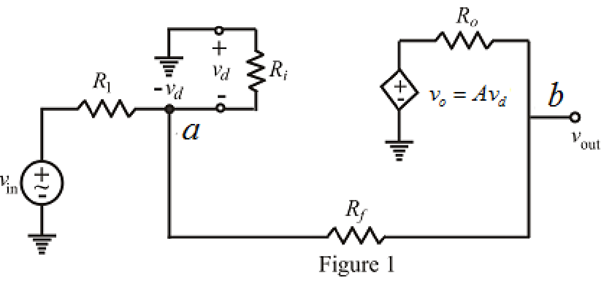
Refer to Figure 1,
Apply Kirchhoff’s current law at node
Here,
Rearrange equation (1),
Apply Kirchhoff’s current law at node
Here,
Substitute
Rearrange for
Substitute
Rearrange the equation for
Modify the equation as,
Write the equation to find voltage
So, the Thevenin voltage is
To find equivalent resistance of a circuit the independent voltage source replaced by short circuit and load resistor is disconnected and
The redrawn circuit diagram is given in Figure 2,
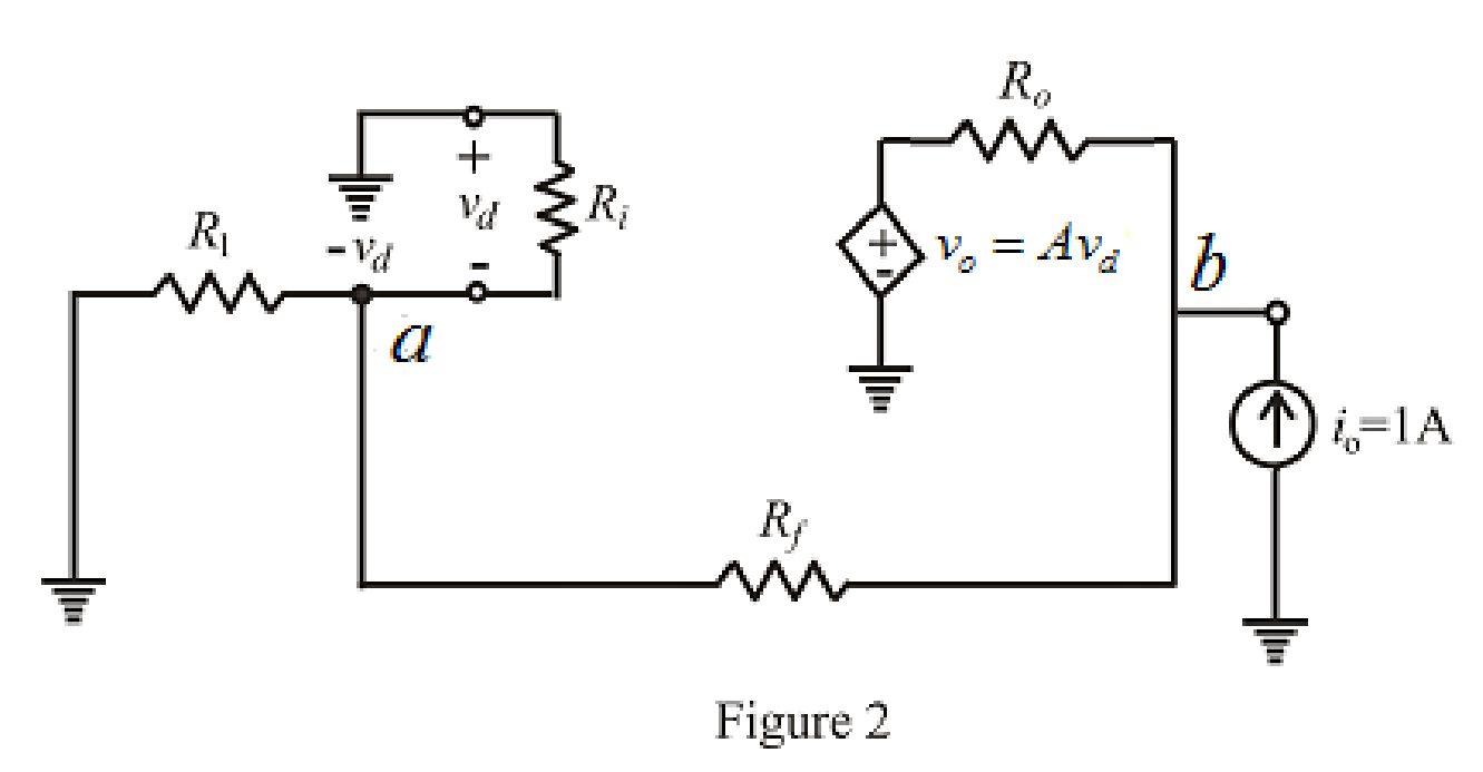
Refer to the redrawn Figure 2,
Apply Kirchhoff’s current law at node
Rearrange for
Apply Kirchhoff’s current law at node
Substitute
Substitute
Rearrange for
The expression for the Thevenin equivalent resistance is as follows,
Substitute
So, the Thevenin equivalent resistance is
The Thevenin equivalent circuit is drawn as shown in Figure 3,
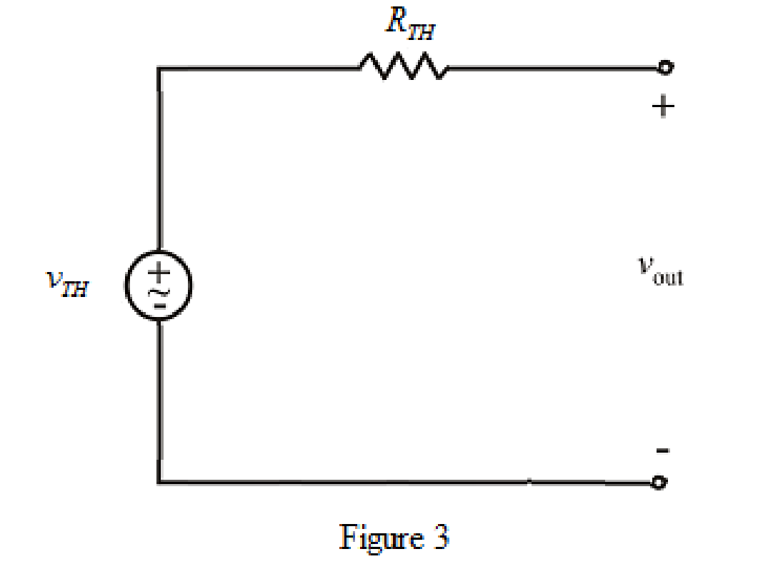
Conclusion:
Thus, the Thevenin voltage is
Want to see more full solutions like this?
Chapter 5 Solutions
Loose Leaf for Engineering Circuit Analysis Format: Loose-leaf


- Note: Consider ideal OP Amps SOKS ww 260KL Vi ww ww Vo 4mv ww DETERMINE Aufo Vol.arrow_forwardThe Junction Gate Field Effect Transistor is one of the simplest types of fieldeffect transistor. It is a three-terminal semiconductor device .One of its function is, it serve as an amplifier. As an Engineer you are to design a single stage JFET Amplifier. Explain in your own words this circuit operates, identifyingarrow_forwardA single stage amplifier has a voltage gain of 60. The collector load RC = 50092 and the input impedance is 1k02. Calculate the overall gain when two such stages are cascaded through R-C coupling.arrow_forward
- 5.39 For the op amp circuit in Fig. 5.76, determine the value of v2 in order to make v, = -16.5 V. 10 k2 50 k2 -3 V O 20 k2 V2 O + 50 k2 5 V oarrow_forward3. Problem 5.29: Determine the voltage gain vo/vi of the following OP Amp circuit R1 R2 R2 R1arrow_forwarda) List and explain the plannar process technology as applied to IC fabrication b) A circuit is built around a bi-polar NPN transistor. The Base network has a resistor (RB) and diode (DB) in series with the cathode of the diode connected to the base while the collector is connected to a power supply (Voc) through a resistor (Rc). Ifthe emitter is connected to ground: 1 Draw the circuit ii. Provide all the masking layout of the circuitarrow_forward
- For the op-amp circuit below, which of the following statements is true? Let Ad = 100,000 and + Vsat +5 V. +6 V 12ka 3ka. 470 2 - 6 V LED When Vi = 5 V, the LED is blinking. O When Vi = 5 V, the LED is ON. When Vi = 5 V, the LED is OFF. O When Vi = 5 V, the LED will be damaged due to excessive current and voltage.arrow_forwardFigure 5.52 For Prob. 5.13. 5.14 Determine the output voltage v, in the circuit of Fig. 5.53. 10 k2 10 kQ 20 kQ 5 mA 5 k2 Figure 5.53 For Prob. 5.14. er work. Section 5.4 Inverting Amplifierarrow_forwardVD- R1 R2 A VOUT VIN VD+ R3 R4 Figure 5.27 Differential amplifier using op amp, arranged with dashed-line connections to measure CMRR of op amp.arrow_forward
- HW26 5.70 Determine v, in the op amp circuit of Fig. 5.96. 30 ΚΩ 40 kQ ww ww 10 ΚΩ A 20 k2 ww- 1V 60 kQ 10 k2 ww 10 k2 2 V 20 Ω w 10 k2 ww В 3V 10 k2 4V 14 wwHarrow_forward5.59 In the op amp circuit of Fig. 5.86, determine the voltage gain v,/vg. Take R = 10 k2. 2R 4R R R Vsarrow_forwardA piezoelectric force transducer has a charge sensitivity of 20 pC/N. It is connected to a charge amplifier and overall gain of transducer and amplifier is 50 mV/N. The gain of amplifier is O 2.5mV/pC O 1mV/pC O 1.5mV/pC O 4mV/pCarrow_forward
 Introductory Circuit Analysis (13th Edition)Electrical EngineeringISBN:9780133923605Author:Robert L. BoylestadPublisher:PEARSON
 Delmar's Standard Textbook Of ElectricityElectrical EngineeringISBN:9781337900348Author:Stephen L. HermanPublisher:Cengage Learning
 Programmable Logic ControllersElectrical EngineeringISBN:9780073373843Author:Frank D. PetruzellaPublisher:McGraw-Hill Education
 Fundamentals of Electric CircuitsElectrical EngineeringISBN:9780078028229Author:Charles K Alexander, Matthew SadikuPublisher:McGraw-Hill Education
 Electric Circuits. (11th Edition)Electrical EngineeringISBN:9780134746968Author:James W. Nilsson, Susan RiedelPublisher:PEARSON
 Engineering ElectromagneticsElectrical EngineeringISBN:9780078028151Author:Hayt, William H. (william Hart), Jr, BUCK, John A.Publisher:Mcgraw-hill Education,