
Concept explainers
Videos
(a)
Find the power absorbed by a
(a)
Answer to Problem 66E
The power absorbed by a
Explanation of Solution
Given data:
The resistance of the load is
Formula used:
The expression for the equivalent resistor when resistors are connected in series is as follows:
Here,
The expression for the equivalent resistor when resistors are connected in parallel is as follows:
Here,
The
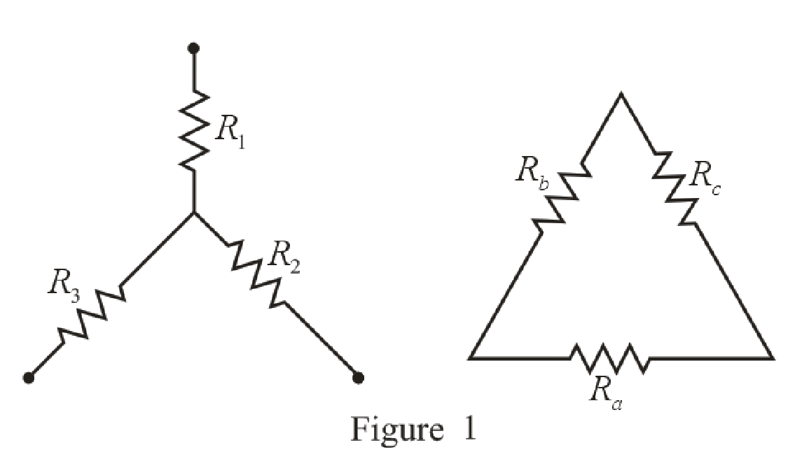
Refer to the redrawn Figure 1:
The expression for the conversion of
Here,
Calculation:
The redrawn circuit diagram is given in Figure 2.
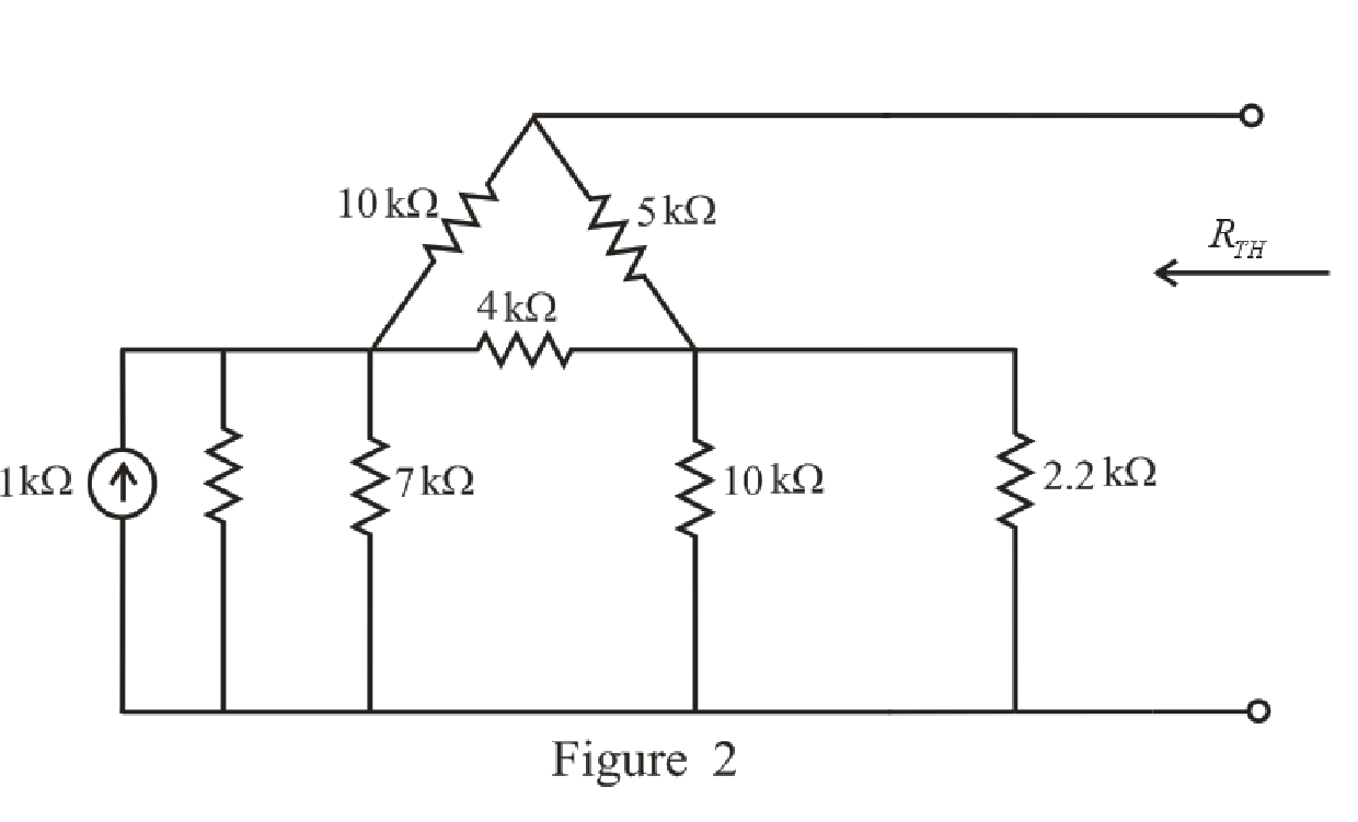
Refer to the redrawn Figure 2:
Substitute
Rearrange the equation for
Substitute
Rearrange the equation for
The simplified circuit diagram is given in Figure 3:
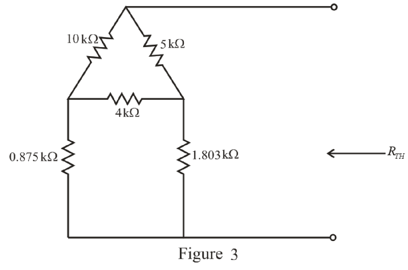
Refer to the redrawn Figure 3:
The
Substitute
Substitute
Substitute
The simplified circuit diagram is given in Figure 4.
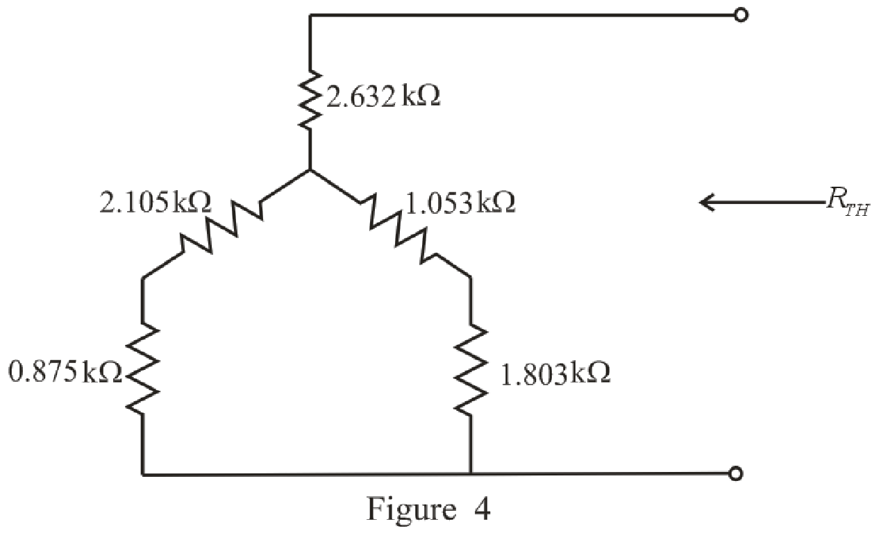
Refer to the redrawn Figure 4.
Substitute
Substitute
The simplified circuit diagram is given in Figure 5.
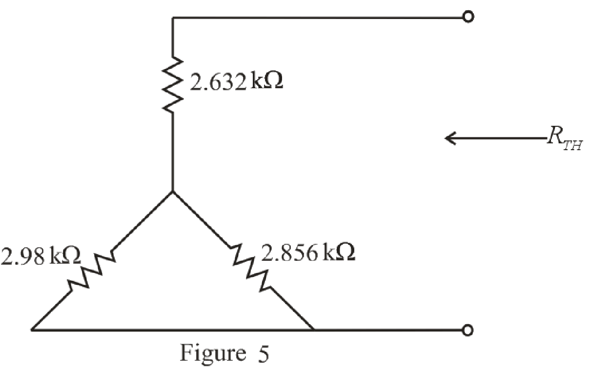
Refer to the redrawn Figure 5:
Substitute
Rearrange the equation for
The simplified circuit diagram is given in Figure 6.
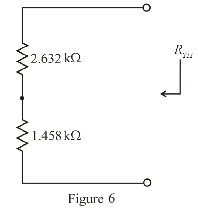
Refer to the redrawn Figure 6:
Substitute
The simplified circuit diagram is given in Figure 7.
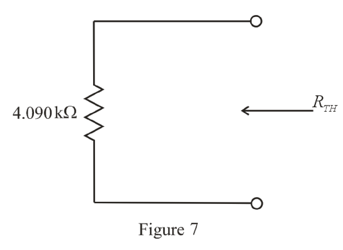
Refer to the redrawn Figure 7:
So, the Thevenin equivalent resistance is
The simplified circuit diagram is given in Figure 8.
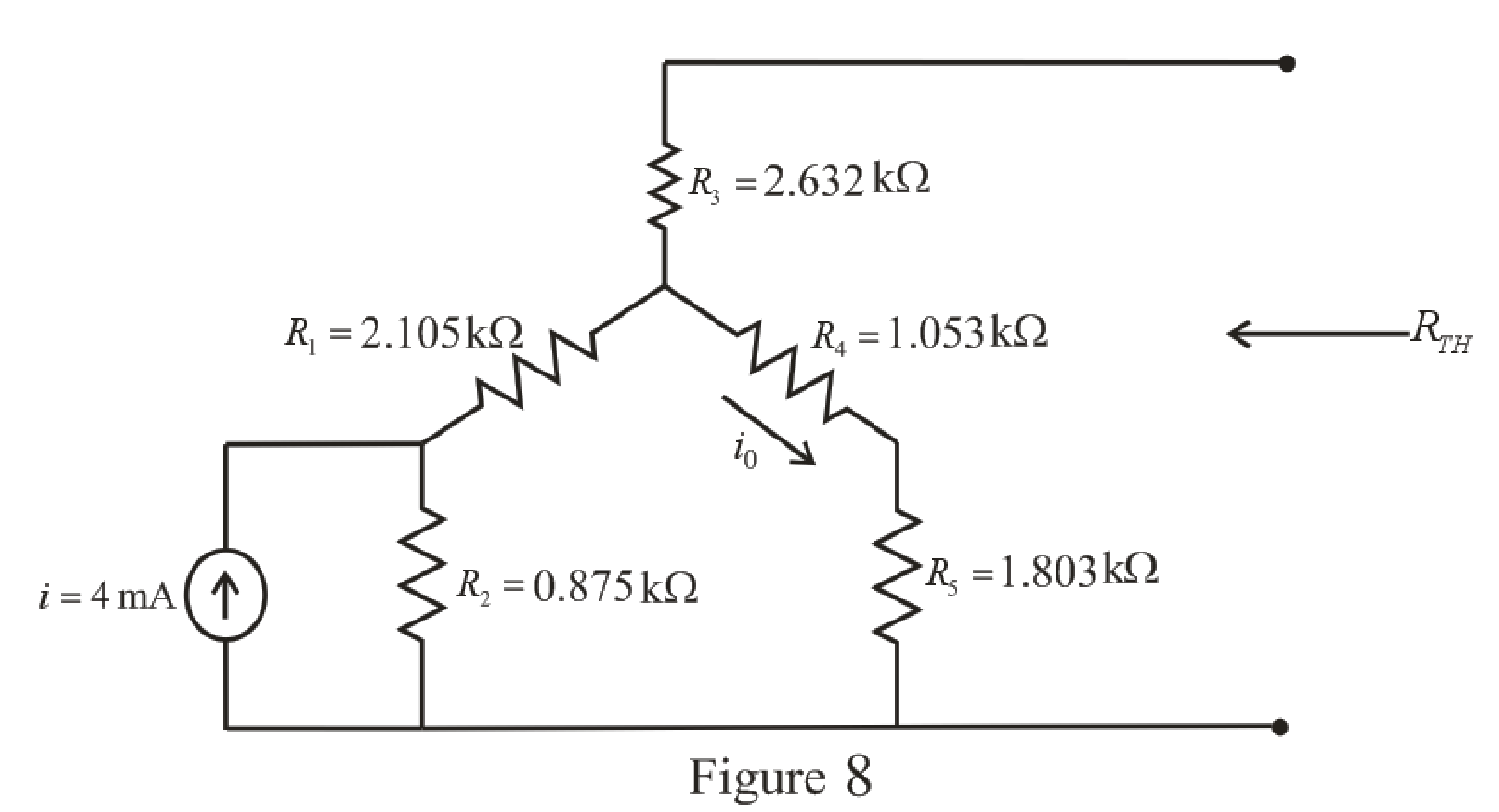
Refer to the redrawn Figure 8:
The
The expression for the current flowing through
Here,
Substitute
The expression for the Thevenin voltage is as follows:
Here,
Substitute
So, the Thevenin voltage of the circuit is
The redrawn circuit diagram is given in Figure 9.
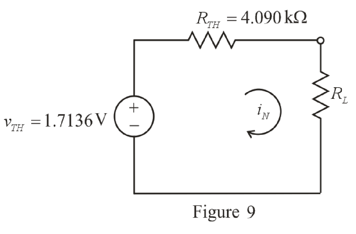
Refer to the redrawn Figure 9:
The expression for the power absorbed by the load resistor is as follows:
Here,
Substitute
Conclusion:
Thus, the power absorbed by a
(b)
Find the power absorbed by a
(b)
Answer to Problem 66E
The power absorbed by a
Explanation of Solution
Given data:
The resistance of the load is
Calculation:
Refer to the redrawn Figure 9:
Substitute
Conclusion:
Thus, the power absorbed by a
(c)
Find the power absorbed by a
(c)
Answer to Problem 66E
The power absorbed by a
Explanation of Solution
Given Data:
The resistance of the load is
Calculation:
Refer to the redrawn Figure 9:
Substitute
Conclusion:
Thus, the power absorbed by a
(d)
Find the power absorbed by a
(d)
Answer to Problem 66E
The power absorbed by a
Explanation of Solution
Given Data:
The resistance of the load is
Calculation:
Refer to the redrawn Figure 9:
Substitute
Conclusion:
Thus, the power absorbed by a
Want to see more full solutions like this?
Chapter 5 Solutions
Loose Leaf for Engineering Circuit Analysis Format: Loose-leaf


- Find the voltage across each resistor in Fig. 5.116 if R1 = 2R3 and R2 =7R3. E 60 V R₁ R₂ R3 M M M 15² +15+15+ UNIVERSITYarrow_forward5.13 Find v, and i, in the circuit of Fig. 5.52. 10 kΩ 1 V 100 k2 90 kN www 10 k2 50 kN + (+ Iarrow_forwardUsing the voltage divider rule or Kirchhoff's voltage law, determine the unknown voltages for the configurations in Fig. 5.119. Do not calculate the current! E₁ + 50 V + E • 3.3 ΚΩ + Vi 6.8 ΚΩ · 4.7 ΚΩ WHI • 10 ΚΩ 30 V 0 + Vx E HI 2 Ω 68 Ω 100 Ω Μ + + 1000 V - UNIVERSarrow_forward
- Homework: Obtain vo in the circuit of the following figure. 5.3 30 V 20 V 4 k2 2 kn 5 kn Answer 20 V www wwarrow_forwardFor the network of Fig. 5.163., Determine Zi? 12 V HH B = 120 To=40 kQ Ilov 300 ΚΩ -8 V FIG. 5.163 Select one: O a. Zi = 236 KQ O b. Zi = 238 k O c. Zi = 237 KQ O d. Zi = 239 KQ • 5.6 ΚΩ Varrow_forward1. For each configuration in Fig. 5.88, find the individaal (not combinations of) elements (voltage sources and/or resis- Lors) that are in serics. N R (a) (b) (e) (4) 一章arrow_forward
- Question 30 a) Employ Thévenin's theorem to obtain a simple two-component equivalent of the circuit shown in Fig. 5.72. b) Use your equivalent circuit to determine the power delivered to a 100 2 resistor connected to the open terminals. c) Verify your solution by analyzing the original circuit with the same 100 2 resistor connected across the open terminals. 45 Ω QTVⒸ 1 0.7 V FIGURE 5.72 75 Ω ww 122 02 220 Ω wwo 0.3 Aarrow_forwardDraw neatly the block diagram of the circuit in Fig. 5. O 6V R1 TR1 R2 LDR O OV Figure 5 ^^ 多arrow_forwardHomework: Obtain vo in the circuit of the following figure. 5.3 30 V 20 V 4 kS2 2 k2 5 k2 Answer 20 Varrow_forward
- For the network of Fig. 5.172: Determine Zi 24 V 4.3 ΚΩ 560 kQ V R, 10μF with 1 KQ Z FIG. 5.172 Select one: O a. Zi 166.52 ohms O b. Zi - 606.52 ohms O c. Zi = 661.52 ohms O d. Zi 616.52 ohms = +41 10µF HH B=80 R₁2.7k02 <arrow_forwardQuestion 27 a) Obtain the Norton equivalent of the network connected to R₂ in Fig. 5.70. Obtain the Thévenin equivalent of the same network. b) c) Use either to calculate i, for R₂ = 0 2,1 2, 4.923 , and 8.107 2. 1 A FIGURE 5.70 5Ω 5Ω 0.8 Ω 202 RLarrow_forwardDetermine V in the circuit of Fig. 5. 100 V 16 Ω Μ 15Ω 35 Ω Fig. 5. 30 Ω 10 Ω Μ 1292 20 Ωarrow_forward
 Introductory Circuit Analysis (13th Edition)Electrical EngineeringISBN:9780133923605Author:Robert L. BoylestadPublisher:PEARSON
 Delmar's Standard Textbook Of ElectricityElectrical EngineeringISBN:9781337900348Author:Stephen L. HermanPublisher:Cengage Learning
 Programmable Logic ControllersElectrical EngineeringISBN:9780073373843Author:Frank D. PetruzellaPublisher:McGraw-Hill Education
 Fundamentals of Electric CircuitsElectrical EngineeringISBN:9780078028229Author:Charles K Alexander, Matthew SadikuPublisher:McGraw-Hill Education
 Electric Circuits. (11th Edition)Electrical EngineeringISBN:9780134746968Author:James W. Nilsson, Susan RiedelPublisher:PEARSON
 Engineering ElectromagneticsElectrical EngineeringISBN:9780078028151Author:Hayt, William H. (william Hart), Jr, BUCK, John A.Publisher:Mcgraw-hill Education,