
Concept explainers
Videos
Employ Δ–Y conversion techniques as appropriate to determine Rin as labeled in Fig. 5.101.
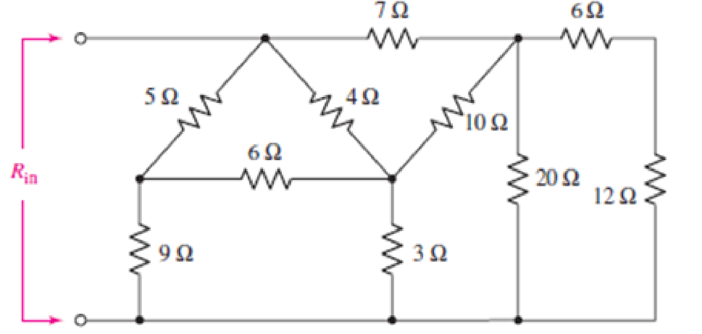
FIGURE 5.101
Employ Δ–Y conversion techniques as appropriate to determine
Answer to Problem 62E
The value of
Explanation of Solution
Formula used:
The expression for the equivalent resistor when resistors are connected in series is as follows:
Here,
The expression for the equivalent resistor when resistors are connected in parallel is as follows:
Here,
The
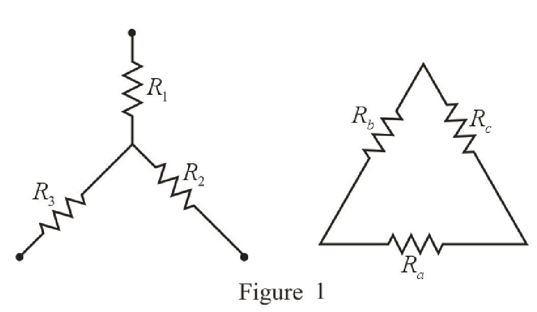
Refer to the redrawn Figure 1:
The expression for the conversion of
Here,
The expression for the conversion of
Calculation:
The redrawn circuit diagram is given in Figure 2:
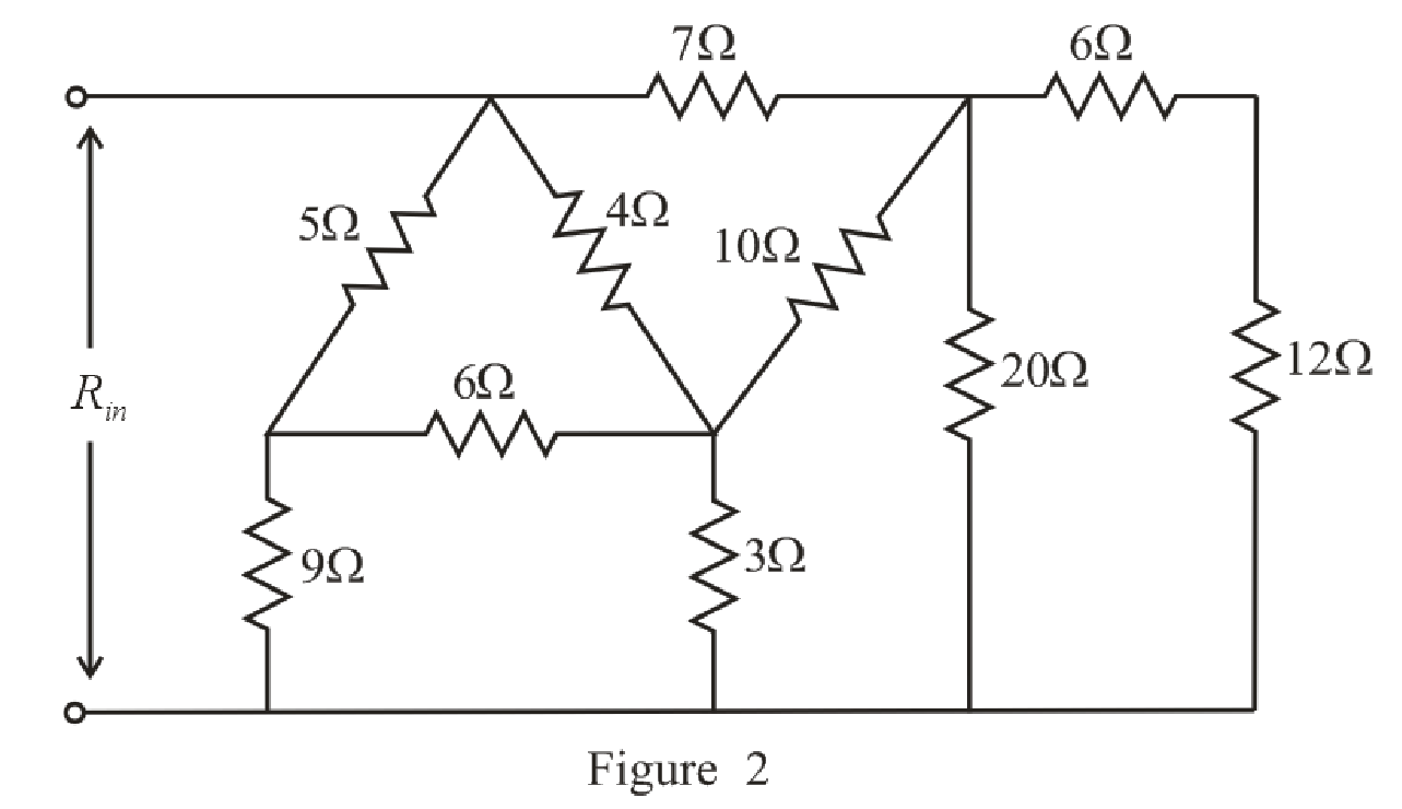
Refer to the redrawn Figure 2:
Substitute
The simplified circuit diagram is given in Figure 3.
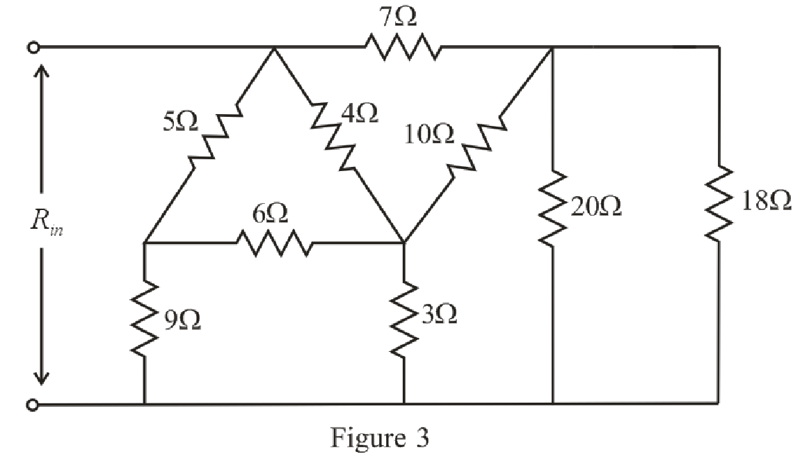
Refer to the redrawn Figure 3:
Substitute
Rearrange the equation for
The simplified circuit diagram is given in Figure 4.
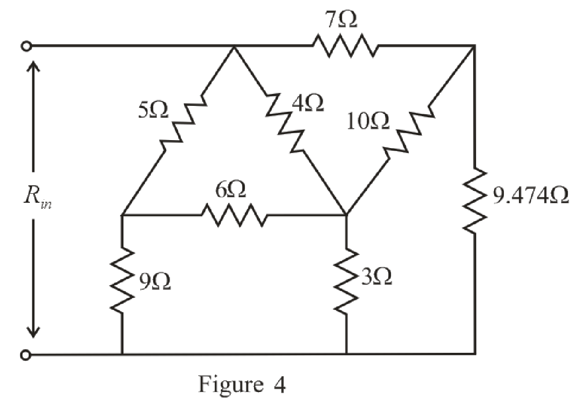
Refer to the redrawn Figure 4:
The
Substitute
Substitute
Substitute
The simplified circuit diagram is given in Figure 5:
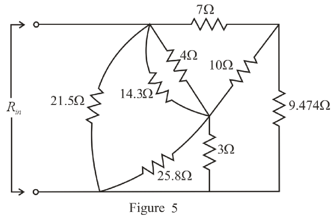
Refer to the redrawn Figure 5:
Substitute
Rearrange the equation for
Substitute
Rearrange the equation for
The simplified circuit diagram is given in Figure 6.
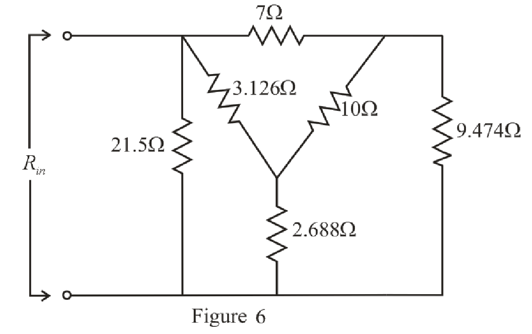
Refer to the redrawn Figure 6:
Substitute
Substitute
Substitute
The simplified circuit diagram is given in Figure 7.
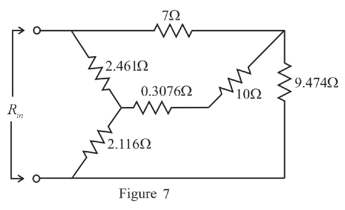
Refer to the redrawn Figure 7:
Substitute
The simplified circuit diagram is given in Figure 8:
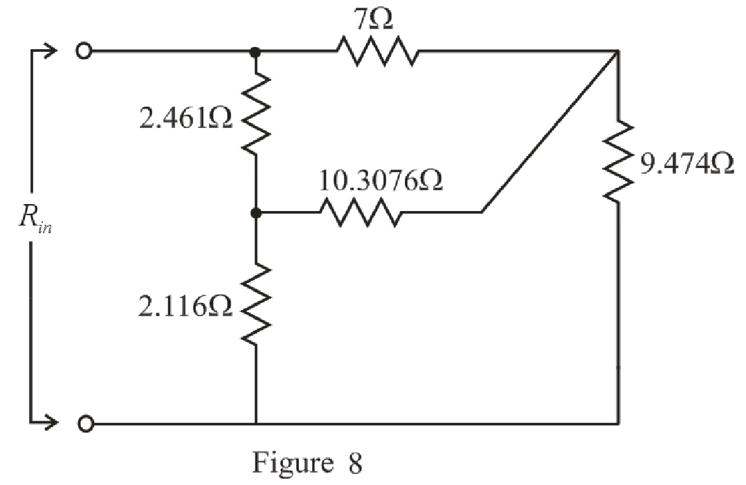
Refer to the redrawn Figure 8:
The
Substitute
Substitute
Substitute
The simplified circuit diagram is given in Figure 9:
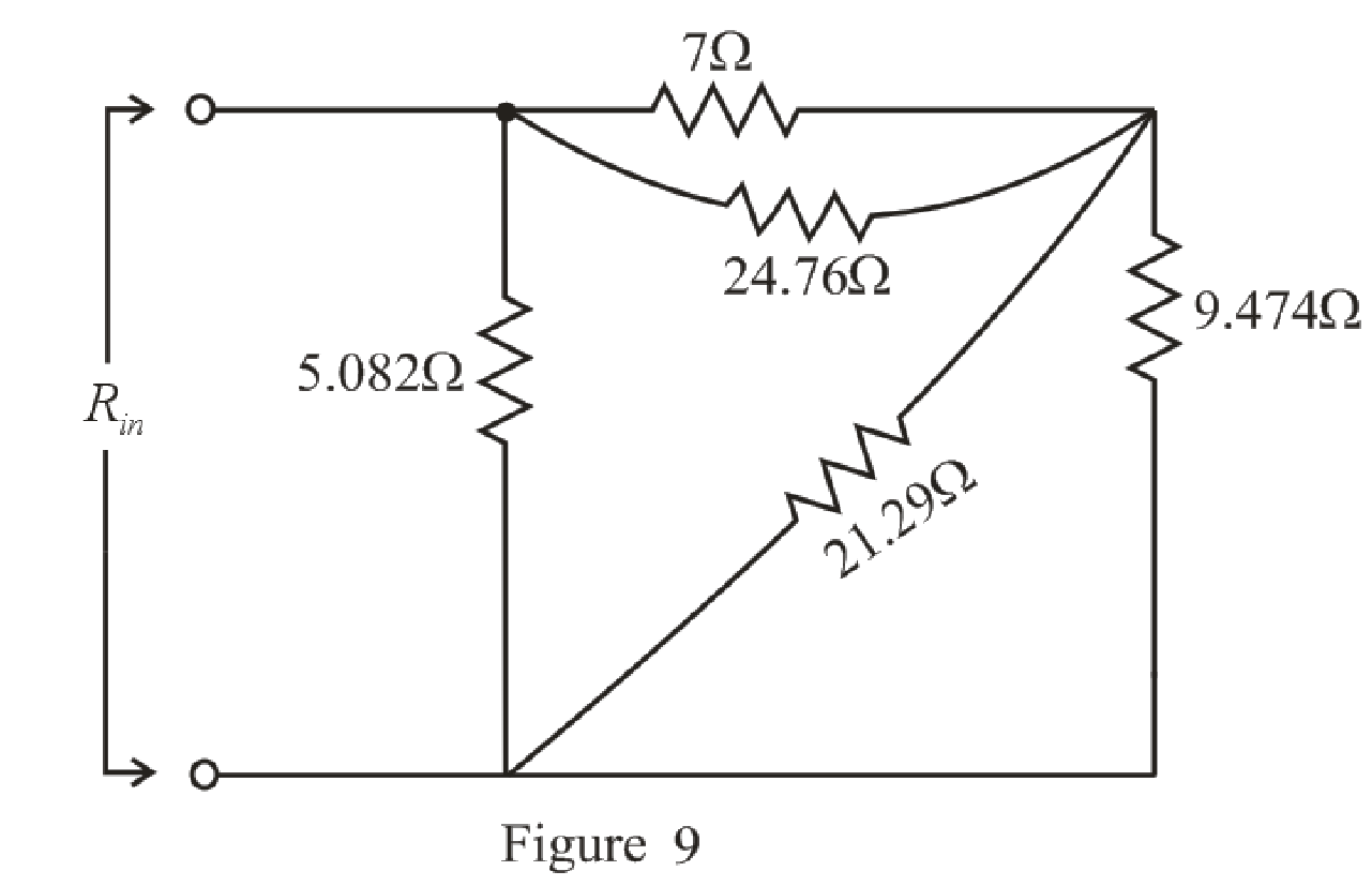
Refer to the redrawn Figure 9:
Substitute
Rearrange the equation for
Substitute
Rearrange the equation for
The simplified circuit diagram is given in Figure 10.
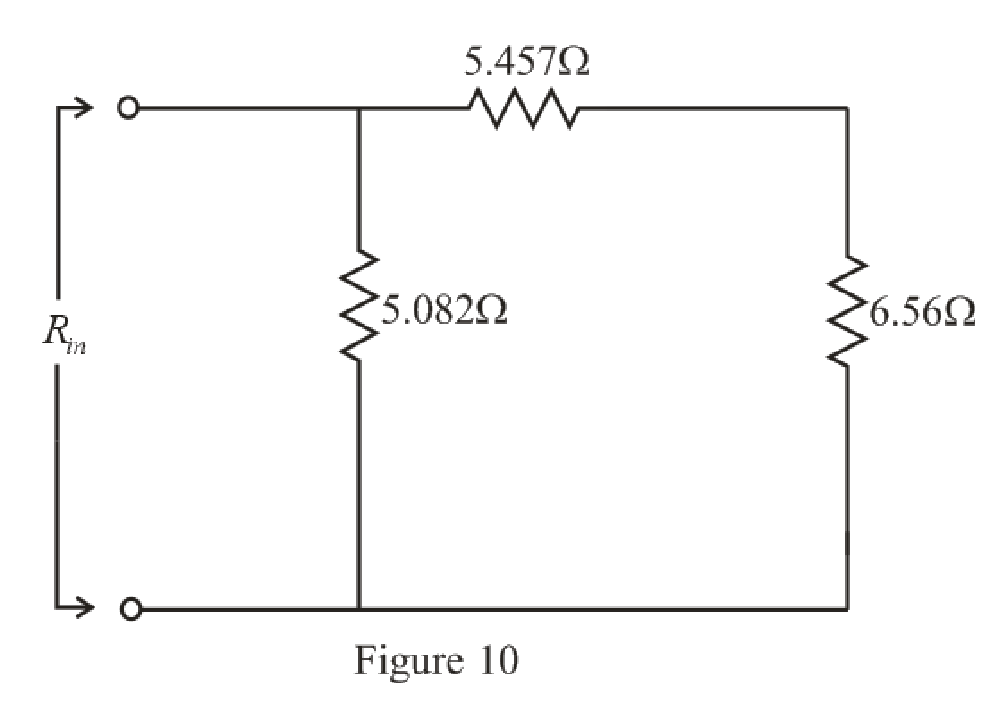
Refer to the redrawn Figure 10:
Substitute
The simplified circuit diagram is given in Figure 11.
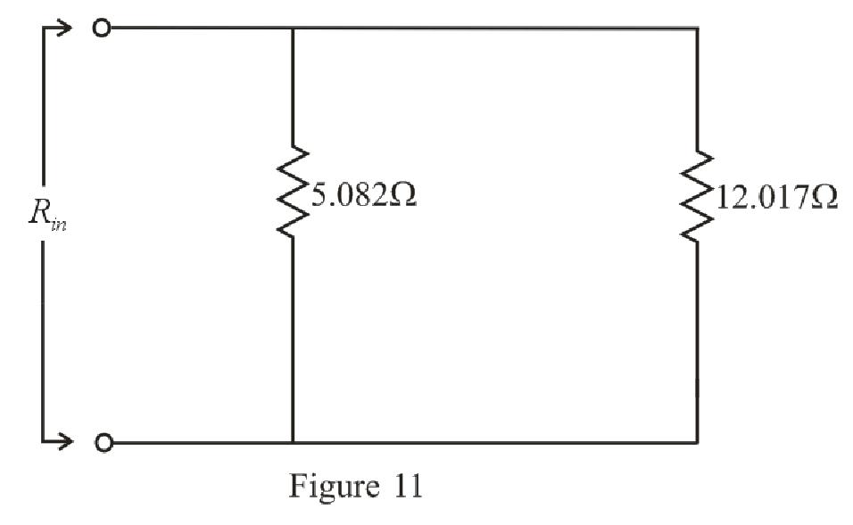
Refer to the redrawn Figure 11:
Substitute
Rearrange the equation for
The simplified circuit diagram is given in Figure 12.
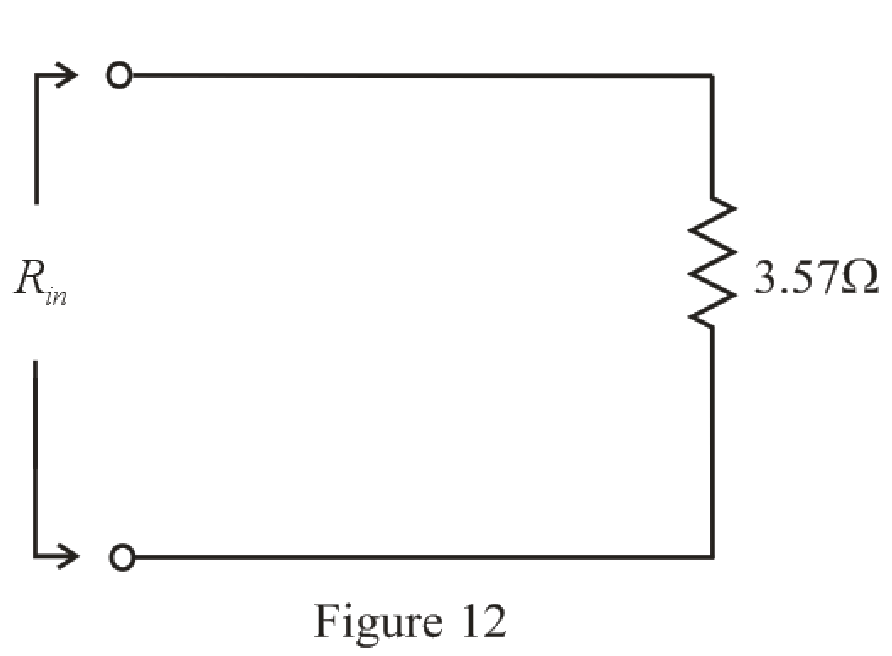
Conclusion:
Thus, the value of
Want to see more full solutions like this?
Chapter 5 Solutions
Loose Leaf for Engineering Circuit Analysis Format: Loose-leaf
Additional Engineering Textbook Solutions
Electric Motors and Control Systems
Basic Engineering Circuit Analysis
ANALYSIS+DESIGN OF LINEAR CIRCUITS(LL)
Microelectronics: Circuit Analysis and Design
Electric machinery fundamentals
Electrical Engineering: Principles & Applications (7th Edition)


- 5.2 For the circuit of Fig. 5.7, use superposition to obtain the voltage across each current source. Ans: Viha = 9.180 V, v2zA =-1.148 V, UIlay = 1.967 V, v2by = -0.246 V; vI = 11.147 V, vz = -1.394 V. %3D %3D %3D 15 N 12 4i 2 A( 3 Varrow_forward5.66 For the circuit in Fig. 5.93, find v. 25 kQ 40 k2 100 k2 20 k2 20 k2 12 V 10 k2 8 V 4 Varrow_forwardWhat is the ohmmeter reading for each configuration in fig 5.96arrow_forward
- 24. With regard to the circuit represented in Fig. 5.68, first transform both voltage sources to current sources, reduce the number of elements as much as possible, and determine the voltage v3. 6 0 + V3 203 2 Varrow_forwardĐĂNG PHẠM HỒNG PowerPoint LMH_chapter3-part 1-homework [Protected View] & Share View Help Tell me what you want to do Home Insert Design Transitions Animations Slide Show Review File HW17 5.14 Determine the output voltage v, in dhe circuit of Fig 5.53. HW19 10 ka ww 10 ka 20 ka S ma () 5ko 5.24 In the circuit shown in Fig. 5.62, find k in the voltage transfer function vo = ku;. 6. HW18 Ry 5.20 In the circuit of Fig. 5.59, calculate v, of v; = 0. S kl ww ww 2 kS ww R1 R2 9v e 7 HW19 3.24 In the circuit shown in Fig 5.62, find k in the voltage transfer flunction ,- b, R3 8. HW20 5.32 Calculate ir and v, in the cicuit of Fir. 5.70. Find the power dissipated by the 30 k resistor 7 43 a 4 mV ( 60 k2 30 k2arrow_forward74. Find Rin for the circuit of Fig. 5.111. 12 2 6Ω 3Ω Rin 12 2 18 Ω I FIGURE 5.111arrow_forward
- Question 2: Make use of source transformations to first convert all three sources in Fig. 5.65 to voltage sources, then simplify the circuit as much as possible and calculate the voltage , which appears across the 4 Q resistor. Be sure to draw and label your simplified circuit. 10 0 10 0 + V, sv, 3 A 9 A IFIGURE 5.65 wwarrow_forward1. Find the total resistance and current I for each circuit of Fig. 5.71. 60 120 I 200 kl 1 MO E = 60 V E- 10 V 330 kn Rr 0.1 M (b) 15 0 1.2 kfl E = 35 V- 25 0 25 1 101 E = 120 V R 4.5 kfl 25 N 101 3 kfl 1.3 kn 2.2 kl (c) (d)arrow_forwardFor the circuit in Fig. 5.88, composed of standard values: a. Which resistor will have the most impact on the total resistance? b. On an approximate basis, which resistors can be ignored when determining the total resistance? c. Find the total resistance, and comment on your results for parts (a) and (b).arrow_forward
- For the series configuration in Fig. 5.92, constructed using standard value resistors: a.) Without making a single calculation, which resistive element will have the most voltage across it? Which will have the least? b.) Which resistor will have the most impact on the total resistance and the resulting current? Find the total resistance and the current.arrow_forwardFor the series configuration in Fig . 5.98 constructed using standard value resistor without making a single calculation, which resistive element will have the most voltage across it? Which will have the least? which resistor will have the most impact on the total resistance and the the resulting current ? Find the total resistance and the current. Find the voltage across each element and review your response to part (a)arrow_forwardFor the network of Fig. 5.172: Determine Zi 24 V 4.3 ΚΩ 560 kQ V R, 10μF with 1 KQ Z FIG. 5.172 Select one: O a. Zi 166.52 ohms O b. Zi - 606.52 ohms O c. Zi = 661.52 ohms O d. Zi 616.52 ohms = +41 10µF HH B=80 R₁2.7k02 <arrow_forward
 Introductory Circuit Analysis (13th Edition)Electrical EngineeringISBN:9780133923605Author:Robert L. BoylestadPublisher:PEARSON
 Delmar's Standard Textbook Of ElectricityElectrical EngineeringISBN:9781337900348Author:Stephen L. HermanPublisher:Cengage Learning
 Programmable Logic ControllersElectrical EngineeringISBN:9780073373843Author:Frank D. PetruzellaPublisher:McGraw-Hill Education
 Fundamentals of Electric CircuitsElectrical EngineeringISBN:9780078028229Author:Charles K Alexander, Matthew SadikuPublisher:McGraw-Hill Education
 Electric Circuits. (11th Edition)Electrical EngineeringISBN:9780134746968Author:James W. Nilsson, Susan RiedelPublisher:PEARSON
 Engineering ElectromagneticsElectrical EngineeringISBN:9780078028151Author:Hayt, William H. (william Hart), Jr, BUCK, John A.Publisher:Mcgraw-hill Education,