
Concept explainers
Videos
5.1 through 5.6 For the beam and loading shown, (a) draw the shear and bending-moment diagrams, (b) determine the equations of the shear and bending-moment curves.
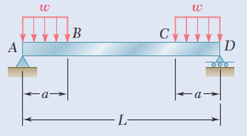
Fig. P5.6
(a)
To draw: The shear and bending-moment diagrams.
Explanation of Solution
Determine the reactions of the beam.
Show the free-body diagram of the entire beam as in Figure 1.

Determine the vertical reaction at point D by taking moment about point A.
Determine the vertical reaction at point A by resolving the vertical component of forces.
Substitute wa for
Determine the horizontal direction at point A by resolving the horizontal component of forces.
Show the free-body diagram of the section 1-1 as in Figure 2.
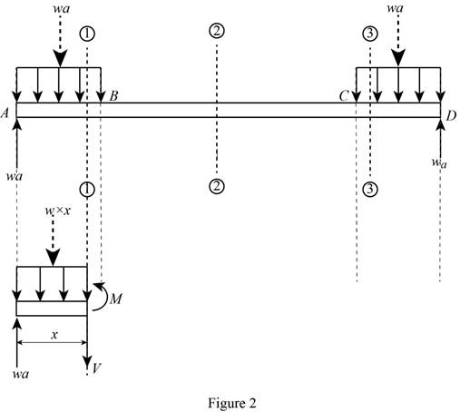
Determine the shear force at the section by resolving the vertical component of forces.
Determine the moment at the section by taking moment about the section.
Show the free-body diagram of the section 2-2 as in Figure 3.
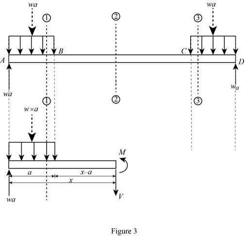
Determine the shear force at the section by resolving the vertical component of forces.
Determine the moment at the section by taking moment about the section.
Show the free-body diagram of the section 3-3 as in Figure 4.

Determine the shear force at the section by resolving the vertical component of forces.
Determine the moment at the section by taking moment about the section.
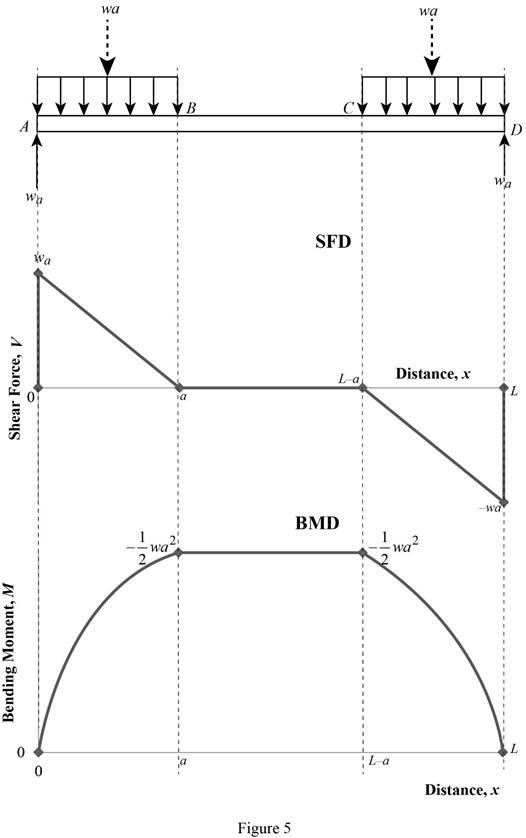
Shear force and bending moment values:
Show the calculated shear force and bending moment values as in Table 1.
| Location (x) | Shear force (V) | Bending Moment (M) |
| A | wa | 0 |
| B (1-1) | 0 | |
| B (2-2) | 0 | |
| C (2-2) | 0 | |
| C (3-3) | 0 | |
| D | –wa | 0 |
Plot the shear force and bending moment diagrams as in Figure 5.
(b)
The equations of the shear and bending-moment curves.
Answer to Problem 6P
The equation of shear force and bending-moment curves is:
For section AB;
For section BC;
For section CD:
Explanation of Solution
Determine the reactions of the beam.
Show the free-body diagram of the entire beam as in Figure 6.

Determine the vertical reaction at point D by taking moment about point A.
Determine the vertical reaction at point A by resolving the vertical component of forces.
Substitute wa for
Determine the horizontal direction at point A by resolving the horizontal component of forces.
Show the free-body diagram of the section 1-1 as in Figure 7.
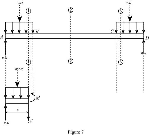
Determine the shear force at the section by resolving the vertical component of forces.
Determine the moment at the section by taking moment about the section.
Show the free-body diagram of the section 2-2 as in Figure 8.

Determine the shear force at the section by resolving the vertical component of forces.
Determine the moment at the section by taking moment about the section.
Show the free-body diagram of the section 3-3 as in Figure 9.
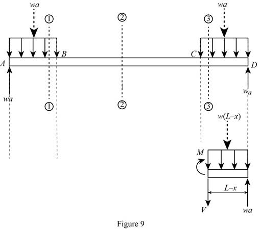
Determine the shear force at the section by resolving the vertical component of forces.
Determine the moment at the section by taking moment about the section.
Therefore, the equation of shear force and bending-moment curves is:
For section AB;
For section BC;
For section CD:
Want to see more full solutions like this?
Chapter 5 Solutions
Mechanics of Materials, 7th Edition


- - -.... .. . and 5.8 beam and loading shown, and determine the maximum absolute value (a) of the shear, (b) of the bending moment. Draw the shear and bending-moment diagrams for the 200 N 200 N 500 N 200 N A C D' E 300 225 300 225 Dimensions in mm Fig. P5.8arrow_forwardDetermine (a) the equations of the shear and bending-moment curves for the beam and loading shown, (b) the maximum absolute value of the bending moment in the beamarrow_forwardProblem 5.64 2.5 k/ft Draw the shear, bending moment, and axial force diagrams and the qualitative deflected shape for the frame shown. 12 ft 30 k 12 ft D 20 ft FIG. P5.64arrow_forward
- I need help solving Problem 5.30 5.29) Knowing that P = Q = 480 N, determine (a) the distance a for which the absolute value of the bending moment in the beam is as small as possible, (b) the corresponding maximum normal stress due to bending. (See hint of Prob. 5.27. 5.30) Solve Prob. 5.29, assuming that P = 480 N and Q = 320 N.arrow_forward30 kN/m 60 kN PROBLEM 5.10 D. Draw the shear and bending-moment diagrams for the beam and loading shown, and determine the maximum absolute value (a) of the shear, (b) of the bending moment. 2 m 2 m (a) = 72.0kN (b) |Mm = 96.0kN - m Imaxarrow_forwardDetermine (a) the equations of the shear and bending moment curves for the beam and loading shown, (b) the maximum absolute value of the bending moment in the beam.arrow_forward
- PROBLEMS 5.16, 5.17 Draw the shear and bending- moment diagrams for the beam and loading shown, and determine the maximum absolute value (a) of the shear, and (b) of the bending moment. 65 kN 30 kN/m D A -1.2 m→-1.2 m -1.2 m→arrow_forwardDraw the shear and bending-moment diagrams for the beam and loading shown and determine the maximum normal stress due to bending. | 25 kips | 25 kips | 25 kips E A B S12 × 35 6 ft 1 ft 2 ft 2 ft Fig. P5.21arrow_forwardSolve Prob. 7.43 knowing that P= 3wa.(Reference to Problem 7.43):Assuming the upward reaction of the ground on beam AB to be uniformly distributed and knowing that P= wa, (a) draw the shear and bending-moment diagrams, (b) determine the maximum absolute values of the shear and bending moment.arrow_forward
- Using the method of Sec. 7.3, solve Prob. 7.42.(Reference to Problem 7.42):For the beam and loading shown, (a) draw the shear and bending-moment diagrams, (b) determine the maximum absolute values of the shear and bending moment.arrow_forward5.79 For the beam and loading of Prob. 5.78, determine (a) the distance 20 kN/m, (b) the corresponding value of WB. a for which wa = WA 24 kN a = 0.6 m Fig. P5.78 1.8 m- 30 kN 0.3 m B WBarrow_forwardFig. P7.32 A W 2 B 2arrow_forward
 Elements Of ElectromagneticsMechanical EngineeringISBN:9780190698614Author:Sadiku, Matthew N. O.Publisher:Oxford University Press
 Mechanics of Materials (10th Edition)Mechanical EngineeringISBN:9780134319650Author:Russell C. HibbelerPublisher:PEARSON
 Thermodynamics: An Engineering ApproachMechanical EngineeringISBN:9781259822674Author:Yunus A. Cengel Dr., Michael A. BolesPublisher:McGraw-Hill Education
 Control Systems EngineeringMechanical EngineeringISBN:9781118170519Author:Norman S. NisePublisher:WILEY
 Mechanics of Materials (MindTap Course List)Mechanical EngineeringISBN:9781337093347Author:Barry J. Goodno, James M. GerePublisher:Cengage Learning
 Engineering Mechanics: StaticsMechanical EngineeringISBN:9781118807330Author:James L. Meriam, L. G. Kraige, J. N. BoltonPublisher:WILEY