
Concept explainers
Videos
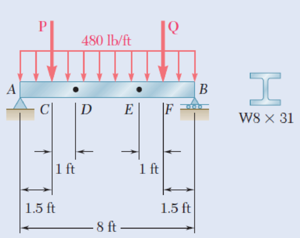
The beam AB supports a uniformly distributed load of 480 lb/ft and two concentrated loads P and Q. The normal stress due to bending on the bottom edge of the lower flange is +14.85 ksi at D and +10.65 ksi at E. (a) Draw the shear and bending-moment diagrams for the beam. (b) Determine the maximum normal stress due to bending that occurs in the beam.
Fig. P5.63
(a)
Draw the shear and bending-moment diagrams for the beam.
Explanation of Solution
Given information:
The normal stress due to bending at the point D is
The normal stress due to bending at the point E is
Refer to Appendix C “Properties of Rolled-Steel Sections” in the textbook.
The section modulus (S) for
Determine the bending moment at point D
Here, the normal stress at point D is
Substitute 14.85 ksi for
Determine the bending moment at point E
Here, the normal stress at point E is
Substitute 10.65 ksi for
Show the free-body diagram of the region DE as in Figure 1.
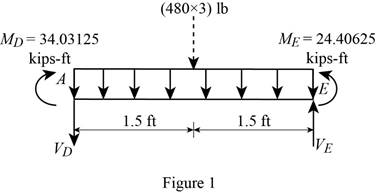
Determine the vertical reaction at point D by taking moment about point E.
Show the free body diagram of the region ACD as in Figure 2.
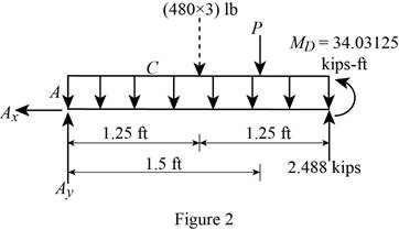
Determine the magnitude of the load P by taking moment about the point A.
Determine the vertical reaction at point A by resolving the vertical component of forces.
Show the free body diagram of the entire beam as in Figure 3.
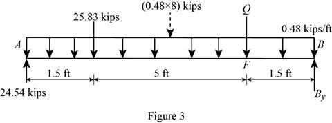
Determine the magnitude of the load P by taking moment about the point B.
Determine the vertical reaction at point A by resolving the vertical component of forces.
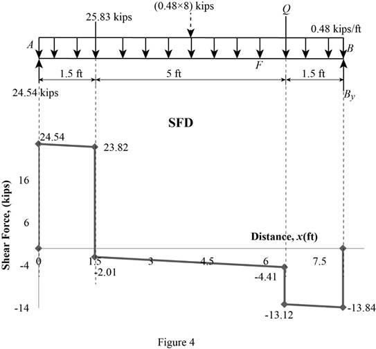
Shear force:
Show the calculation of shear force as follows;
Show the calculated shear force values as in Table 1.
| Location (x) ft | Shear force (V) kips |
| A | 24.54 |
| C (Left) | 23.82 |
| C (Right) | –2.01 |
| F (Left) | –4.41 |
| F (Right) | –13.12 |
| B | –13.84 |
Plot the shear force diagram as in Figure 4.
Bending moment:
Show the calculation of the bending moment as follows;
Show the calculated bending moment values as in Table 2.
| Location (x) ft | Bending moment (M) kips-ft |
| A | 0 |
| C | 36.27 |
| F | 19.77 |
| B | 0 |
Plot the bending moment diagram as in Figure 5.
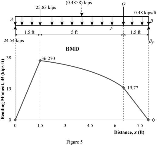
Refer to Figure 5;
The maximum absolute bending moment is
(b)
The maximum normal stress due to bending.
Answer to Problem 63P
The maximum normal stress due to bending is
Explanation of Solution
Given information:
Refer to Appendix C “Properties of Rolled-Steel Sections” in the textbook.
The section modulus (S) for
The maximum absolute bending moment is
Determine the maximum normal stress
Substitute
Therefore, the maximum normal stress due to bending is
Want to see more full solutions like this?
Chapter 5 Solutions
Mechanics of Materials, 7th Edition


- 9. Draw the shearing-force and bending-moment diagrams for the following beams: A cantilever of length 20 m carrying a load of 10 kN at a distance of 15 m from the supported end. A cantilever of length 20 m carrying a load of 10 KN uniformly distributed over the inner 15 m of its length. A cantilever of length 12 m carrying a load of 8 kN, applied 5 m from the supported end, and a load of 2kN/m over its whole length. A beam, 20 m span, simply-supported at each end and carrying a vertical load of 20 kN at a distance 5 m from one support. A beam, 16 m span, simply-supported at each end and carrying a vertical load of 2.5 kN at a distance of 4 m from one support and the beam itself weighing 500 N per i. ii. iii. iv. V. metre.arrow_forward5.7 For the cantilever beam shown in the figure, find (a) the maximum bending stress and its location; and (b) the bending stress at a point 20 mm from the top of the beam on section B. 1.0 kN/m 150 mm C A 2 m- 50 mm 6 m FIG. PS.7arrow_forward5.41 The inverted T-beam supports three concentrated loads as shown in the fig- ure. Find the maximum allowable value of Pif the bending stresses are not to exceed 3.5 ksi in tension and 8 ksi in compression. 14P 1.0 in. D 8 in. 1.0 in. 2 ft 3 ft 3 (t 2 tt - 4 int FIG. PS.41arrow_forward
- 0.6 m 25 kN/m 40 kN 1.8 m 40 KN C 0.6 m D PROBLEM 5.108 (a) Using singularity functions, write the equations for the shear and bending moment for the beam and loading shown. (b) Determine the maximum value of the bending moment in the beam.arrow_forwardd 5.23 Draw the shear and bending-moment diagrams for the beam and loading shown and determine the maximum normal stress due to bending. 80 kN/m 160 kN B C ID A E Hinge- W310 × 60 -2.4 m 1.5 m 1.5 m 0.6 marrow_forwardDraw the shearing-force and bending-moment diagrams for the following beams: 1. A cantilever of length 20 m carrying a load of 10 kN at a distance of 15 m from the supported end. 2. A cantilever of length 20 m carrying a load of 10 kN is uniformly distributed over the inner 15 m of its length. 3. A cantilever of length 12 m carrying a load of 8 kN, applied 5 m from the supported end, and a load of 2kNlm over its whole length.arrow_forward
- I need help solving Problem 5.30 5.29) Knowing that P = Q = 480 N, determine (a) the distance a for which the absolute value of the bending moment in the beam is as small as possible, (b) the corresponding maximum normal stress due to bending. (See hint of Prob. 5.27. 5.30) Solve Prob. 5.29, assuming that P = 480 N and Q = 320 N.arrow_forward5.14. A carriage spring centrally loaded and simply supported at the ends has 10 steel plates each 5 cm wide by 6 mm thíck. If the longest plate is 75 cm long, determine the initial radius of curva- ture of the plates when the greatest bending stress is 800 MPa and the plates are finally straight. Neglecting the loss of energy at impact, find the greatest height from which a mass weighing 250 N may be dropped centrally on the spring without exceeding the limiting bending stress of 800 MPa. Take E = 210 GPa. %3Darrow_forwardPROBLEMS 5.16, 5.17 Draw the shear and bending- moment diagrams for the beam and loading shown, and determine the maximum absolute value (a) of the shear, and (b) of the bending moment. 68 kN 30 kN/m D -1.2 m 1.2 m 1.2 m- Fig. P5.16 PROBLEM 5.21 For the beam and loading shown, bending stress on a transverse sectiarrow_forward
- The rigid bar DEF is welded at point D to the steel beam AB. For the loading shown, determine (a) the equations defining the shear and bending at portion AD of the steel beam AB, (b) the location and magnitude of the largest bending moment. (Hint: Replace the 700 N load applied at F by an equivalent force-couple system at D) 750 N/m B D 000 E 2.4 m X 0.9 m 700 N -1.5 m.arrow_forwardPROBLEM 5.21 For the beam and loading shown, determine the maximum bending stress on a transverse section at C. [Ans. 10.89 MPa] 10 kN 3 kN/m 100 mm 25 de 200 mm B 1.5 m 1.5 m X-X 2.2 m splay E23 Fig. P5.21 Chp Show all 205 14 04/22 ALING • SPARKLING PURDEY'S NATURAL ENERGT REFOCUS Dark Fruits with guarana Paune hp Prien Sem Sysha Scroll Serril Lock F11 F10 F9 Num Lock F8 Page Up F7 F6 Home F5 bert F4 7 Page Down Home End Deletearrow_forwardCurrent Attempt in Progress The moment acting on the cross section of the T- beam has a magnitude of 19 kip-ft and is oriented as shown. Assume b;= 7.0 in., tw=1.50 in., t= 1.00 in., d = 9.5 in. and 0 = 70°. Determine (a) the bending stress at point H. (b) the bending stress at point K. (c) the orientation of the neutral axis relative to the +z axis; show its location on a sketch of the cross section. y Answers: (a) OH = (b) ok= (c) B= MI IH TH K bf H ksi ksi 0arrow_forward
 Elements Of ElectromagneticsMechanical EngineeringISBN:9780190698614Author:Sadiku, Matthew N. O.Publisher:Oxford University Press
 Mechanics of Materials (10th Edition)Mechanical EngineeringISBN:9780134319650Author:Russell C. HibbelerPublisher:PEARSON
 Thermodynamics: An Engineering ApproachMechanical EngineeringISBN:9781259822674Author:Yunus A. Cengel Dr., Michael A. BolesPublisher:McGraw-Hill Education
 Control Systems EngineeringMechanical EngineeringISBN:9781118170519Author:Norman S. NisePublisher:WILEY
 Mechanics of Materials (MindTap Course List)Mechanical EngineeringISBN:9781337093347Author:Barry J. Goodno, James M. GerePublisher:Cengage Learning
 Engineering Mechanics: StaticsMechanical EngineeringISBN:9781118807330Author:James L. Meriam, L. G. Kraige, J. N. BoltonPublisher:WILEY