
Concept explainers
Videos
The switch in Fig. 8.70 is moved from A to B at t = 0 after being at A for a long time. This places the two capacitors in series, thus allowing equal and opposite dc voltages to be trapped on the capacitors. (a) Determine v1(0−), v2(0−), and vR(0−). (b) Find v1(0+), v2(0+), and vR(0+). (c) Determine the time constant of vR(t). (d) Find vR(t), t > 0. (e) Find i(t). (f) Find v1(t) and v2(t) from i(t) and the initial values. (g) Show that the stored energy at t = ∞ plus the total energy dissipated in the 20 kΩ resistor is equal to the energy stored in the capacitors at t = 0.
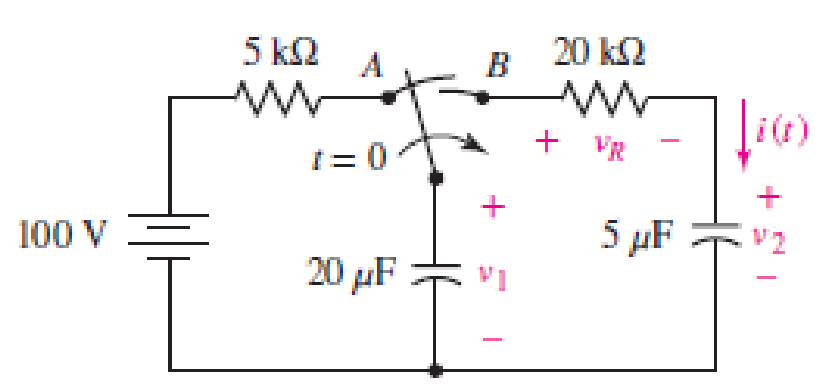
■ FIGURE 8.70
(a)
Find the value of
Answer to Problem 38E
The value of
Explanation of Solution
Given data:
Refer to Figure 8.70 in the textbook.
The switch is moved from
Calculation:
The given circuit is redrawn as shown in Figure 1.
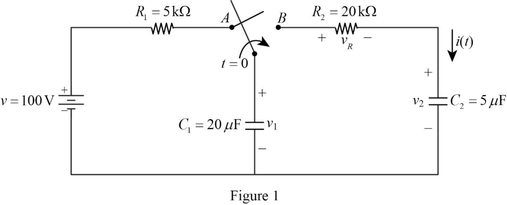
Refer to Figure 1, the voltage across the capacitor
For a DC circuit at steady state condition, when the switch is in position
Now, the Figure 1 is reduced as shown in Figure 2.
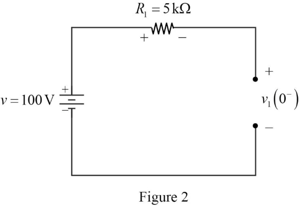
Refer to Figure 2, the voltage source
The voltage across the capacitor
Refer to Figure 2, the resistor
The voltage across the capacitor is always continuous so that,
Conclusion:
Thus, the value of
(b)
Find the value of
Answer to Problem 38E
The value of
Explanation of Solution
Calculation:
For time
Refer to part (a),
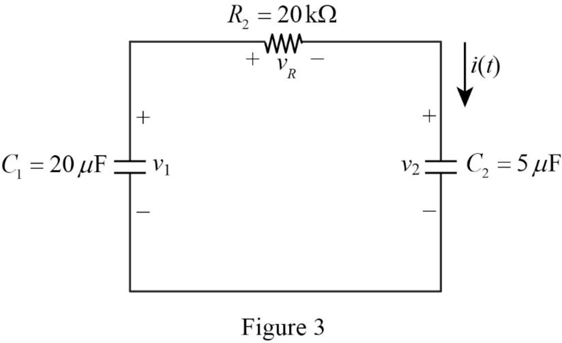
Apply Kirchhoff’s voltage for the circuit shown in Figure 3 for time
Substitute
Conclusion:
Thus, the value of
(c)
Find the value of the time constant.
Answer to Problem 38E
The value of time constant
Explanation of Solution
Formula used:
Write a general expression to calculate the time constant.
Here,
Calculation:
Refer to Figure 3, the capacitors
The equivalent capacitance
Now, the Figure 3 is reduced as shown in Figure 4.
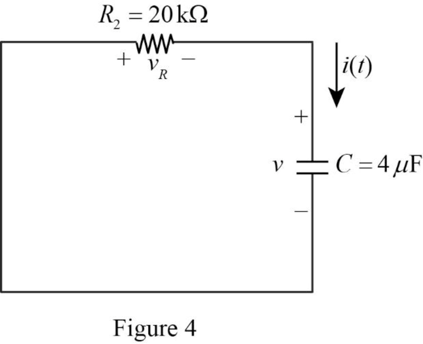
Refer to Figure 4, it shows the
Use equation (1) to find
Substitute
Conclusion:
Thus, the value of time constant
(d)
Find the expression of voltage
Answer to Problem 38E
The expression of voltage
Explanation of Solution
Formula used:
Write a general expression to calculate the voltage response of an
Here,
Refer to Figure 3, the resistor
Substitute
Substitute
Conclusion:
Thus, the expression of voltage
(e)
Find the expression of current
Answer to Problem 38E
The expression of current
Explanation of Solution
Calculation:
Refer to Figure 3, the capacitor
The current
Substitute
Conclusion:
Thus, the expression of current
(f)
Find the value of voltage
Answer to Problem 38E
The value of voltage
Explanation of Solution
Formula used:
Write a general expression to calculate the voltage across the capacitor.
Calculation:
From the given data, the capacitor
Use equation (1) to find the voltage
Substitute
Simplify the above equation to find
Use equation (1) to find the voltage
Substitute
Simplify the above equation to find
Conclusion:
Thus, the value of voltage
(g)
Show that the stored energy at
Explanation of Solution
Formula used:
Write a general expression to calculate the energy stored in a capacitor.
Write a general expression to calculate the energy stored in a resistor.
Here,
Calculation:
Refer to Figure 1, there are two capacitors placed in a circuit. Therefore, the total energy stored in a capacitor is,
Use equation (1) to find
Use equation (1) to find
Substitute equation (7) and (8) in (6).
Substitute
Substitute
Simplify the above equation to find
Refer to part (f),
Substitute
Refer to part (f),
Substitute
Substitute
Substitute
Simplify the above equation to find
Substitute
Simplify the above equation to find
Simplify the above equation to find
Substitute
Add
Therefore,
Therefore, the stored energy at
Conclusion:
Thus, the stored energy at
Want to see more full solutions like this?
Chapter 8 Solutions
Loose Leaf for Engineering Circuit Analysis Format: Loose-leaf


- An AC circuit contains a 24 resistor, a 15.9-mH inductor, and a 13.3F capacitor connected in parallel. The circuit is connected to a 240-V, 400-Hz power supply. Find the following values. XL=XC=IR=AIL=AIC=AP=WVARsL=VARsC=IT=AVA=PF=%=arrow_forwardAn electric circuit contains an 8 ohm resistor in series with an inductor of 0.50 henries and a battery of E volts. At t=0 the current is zero. Find the current at any time t > 0 and the maximum current if E=32e-8tarrow_forwardThe figure below shows a simple RC circuit with a 3.10-μF capacitor, a 3.60-MQ resistor, a 9.00-V emf, and a switch. What are the following exactly 8.50 s after the switch is closed? (a) the charge on the capacitor μC (b) the current in the resistor μA R (c) the rate at which the capacitor is storing energy μW (d) the rate at which the battery is delivering energy μWarrow_forward
- Basic Electrical Engineering: Inductance and Capacitance You are an electrician working in an industrial plant. You discover the problem with a certain machine is a defective capacitor. The capacitor is connected to a 240-V AC circuit. The information on the capacitor reveals that it has a capacitance value of 10 µF and a voltage rating of 240 V AC. The only 10-µF capacitor in the storeroom is marked with a voltage rating 350 VDC. Can this capacitor be used to replace the defective capacitor? Explain your answer.arrow_forwardA 2002 resistor, a 0.01 H inductor and a 100 µF capacitor are connected in series, A DC voltage of 100 V is suddenly applied to the circuit. Find the maximum current and the time at which it occurs.arrow_forwardWith the assumption that the switch in the circuit of given figure has been closed a long, long time. Compute the current flowing through the inductor at t=78.8usarrow_forward
- 8. a). What are the values of the inductor voltage and current and the capacitor voltage and current assuming the switch has been closed for a very long time. VL= IL = Vc = Ic= 10 v 1H V₁ 000 502 HI 292 Ic↓ 1F Vcarrow_forwardswitch is in position 2, circuit will discharge the inductor draw the circuit in discharge phase, the equations for v(t) and i(t) of the inductor for the discharge phase, and determine the time constant for the discharge phasearrow_forwardConsider the circuit shown below, with an initially uncharged capacitor C and two identical resistors R. R O www V I C I₂ R C R At the instant the switch is closed, the current through the capacitor will be: zero At the instant the switch is closed, the current through the right-side resistor will be: V/R, directed Up After the switch has been closed for a very long time, it is opened. The current through the right-side resistor will be V/R, directed Down The switch is closed at t = 0. At t = ~ (long after) the current through the right-side resistor will be: V/2R, directed Down ✓ The switch is closed at t = 0. At t = ~ (long after) the current through the capacitor will be: V/2R, directed Up After the switch has been closed for a very long time, it is ope ed. The current through the be? V/R, directed Down pacitor willarrow_forward
- Capacitors are fundamental electrical components that store energy in the form of an electric field. They consist of two conductors separated by an insulator, known as a dielectric. When a voltage is applied to the capacitor terminals, it accumulates opposite charges on the conductors, creating an electric field between them. What is the total capacitance (C) in farads (F) between terminals A and B in the capacitor arrangement present in the circuit below?arrow_forwardA capacitor that is initially uncharged is connected in series with a resistor and a 300.0 V emf source with negligible internal resistance. Just after the circuit is completed, the current through the resistor is 0.950 mA and the time constant for the circuit is 6.00 s. (A) What is the resistance of the resistor? (B) What is the capacitance of the capacitor?arrow_forwardAn (open) electric circuit consists of an inductor, a resistor, and a capacitor. There is an initial charge of 2 coulombs on the capacitor. At the instant the circuit is closed, a current of 3 amperes is present and a voltage of E(t) = 20 cos t is applied. In this circuit the voltage drop across the resistor is 4 times the instantaneous change in the charge, the voltage drop across the capacitor is 10 times the charge, and the voltage drop across the inductor is 2 times the instantaneous change in the current. Write an initial value problem to model the circuit.arrow_forward
 Delmar's Standard Textbook Of ElectricityElectrical EngineeringISBN:9781337900348Author:Stephen L. HermanPublisher:Cengage Learning