
Concept explainers
Videos
(a)
Find the expression for
(a)
Answer to Problem 48E
The expression for
Explanation of Solution
Formula used:
The expression for the equivalent resistor when resistors are connected in parallel is as follows:
Here,
The expression for the time constant is as follows:
Here,
The expression for the final response is as follows:
Here,
Calculation:
The redrawn circuit diagram is given in Figure 1.
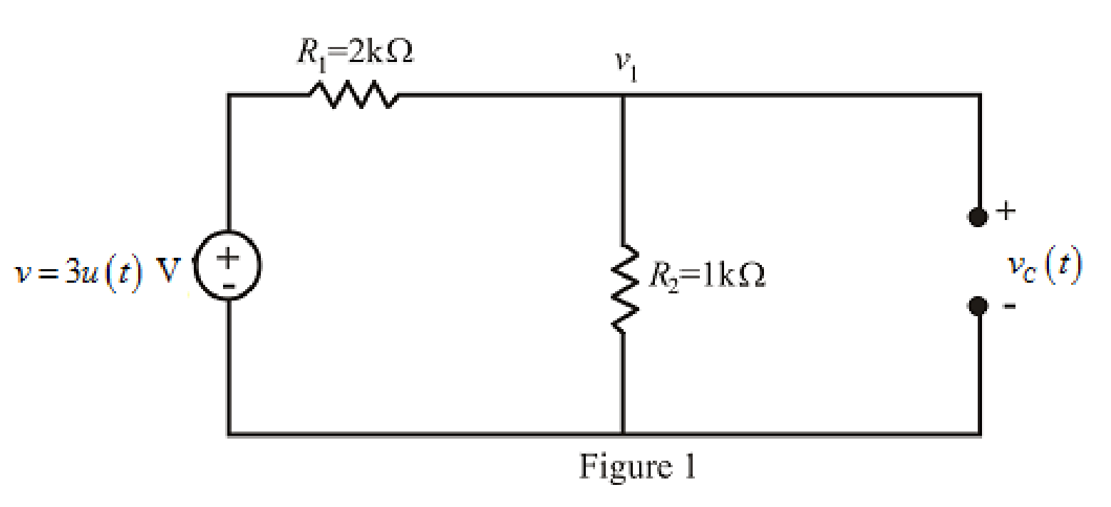
Refer to the redrawn Figure 1:
The given circuit is connected for long time,
So, capacitor behaves as open circuit.
The independent voltage source is unit step function.
The unit-step forcing function as a function of time which is zero for all values of its argument less than zero and which is unity for all positive values of its argument.
Here,
The independent voltage source is:
Substitute
Apply KCL at node 1.
Here,
Substitute
Rearrange for
So, at
The voltage across capacitorat
So,
Substitute
So, the value of the voltage across
Substitute
Rearrange for
So, the voltage
The redrawn circuit diagram is given in Figure 2.
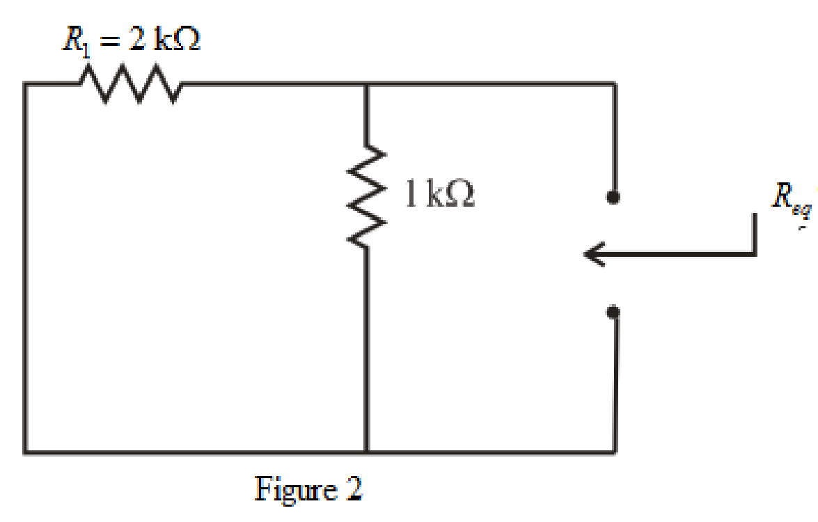
Refer to the redrawn Figure 2:
So, form equation (1),
Rearrange the equation for
The simplified diagram is shown in Figure 3.
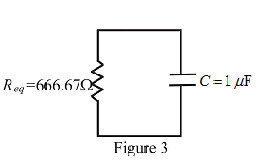
Refer to the redrawn Figure. 3:
Substitute
Substitute
So, the expression for the voltage across the capacitor valid for all values of
Conclusion:
Thus, the expression for
(b)
Sketch
(b)
Explanation of Solution
Given Data:
The range for the time is
Calculation:
Substitute
Substitute
Substitute
Substitute
Substitute
Substitute
Substitute
Substitute
Substitute
The different values of the
The graph for
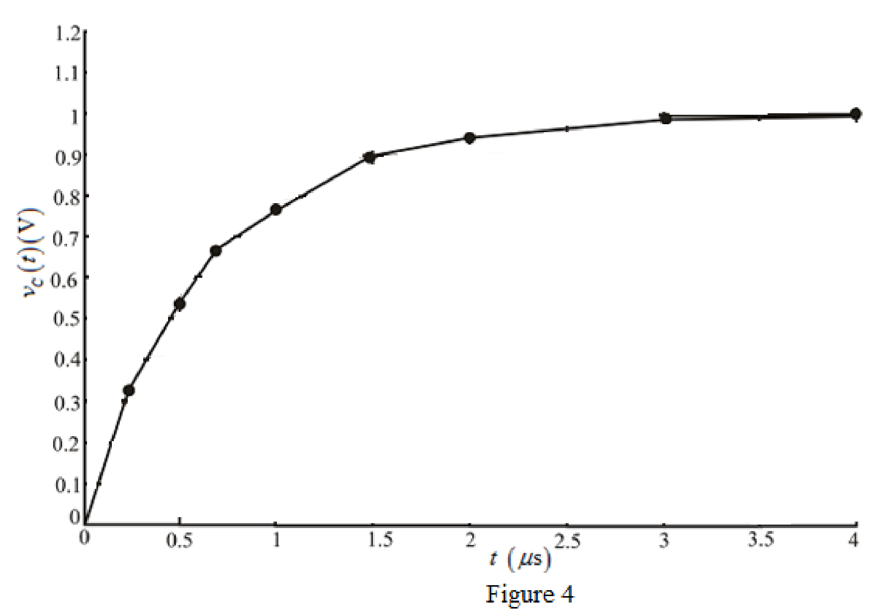
Conclusion:
Thus, the graph for
Want to see more full solutions like this?
Chapter 8 Solutions
Loose Leaf for Engineering Circuit Analysis Format: Loose-leaf


- The switch in the circuit shown has been in position a for a longtime. At t=0, it moves to position b. Find vC(t) for t≥0 2. 8.8 Find i(t) for t≥0 for the circuit Repeat if the 80 Ω resistor isreplaced by a 100 Ω resistorarrow_forwardIn the circuit shown in the figure, the switch is closed for a long time and is opened at t = 0. According to this:(a) Find i(0+) and v(0+).(b) Find (di(0+))/dt(c) Find i(t) for t>0.arrow_forwardObtain an equation which describes the behavior of iA as labeled in Fig. 8.88 over the range of −1 ms ≤ t ≤ 5 ms.arrow_forward
- Consider the given circuit. The switch has been closed for a very long time before opening at t=0s. Determine the expression for Io(t) for t≥0 (in ms) and the expression for the inductor voltage for t≥0.arrow_forward8. A series RC circuit (Fig. 1 below) with one resistor (R=500 M) and one capacitor (C=0.5 µF) is connected to an AC voltage supply which supplies a voltage v=100 sin(1000t+309) (from t=0 to t=∞). The initial charge on the capacitor is Qo = 25 µC and the initial voltage on the capacitor is in the same sense as the AC voltage supply. Obtain the current for t > 0. Qo Figure 1 500 D 0.5 μF 100 V 10 Ω 250 0.01 H Figure 2 iz 250arrow_forwardFigure Q2 shows an RLC circuit with an input voltage v(t) and an output voltage v across the inductor L. Form a state space model for this system using v(t) and iL(t) as the state variables. VL i¿(1) L=2 H v(1) 0.1 F V.(1) 10 Ω Figure Q2arrow_forward
- 3) Consider the circuit below. Assume the switch has been in its initial position for a long time, and it switches position as indicated at t = 0. a. Find v(t) for all t > 0. b. Sketch v(t) as voltage vs. time; annotate critical values on your sketch (see video lectures for example). C. How much energy is stored in the capacitor at t = 0? + ww 50 ΚΩ 12 V t = 0 100 ΚΩ M 100 μF + v(t)arrow_forwardThe inductor current in the circuit is given by 6(1 – e-8t) A (t > 0). (a) Determine the current of the 80 resistor for t > 0. Hint: you need v20: (b) In the limit t→o, does the mathematical solution for igo agree with the circuit at t = 0? Explain your reasoning. Answer: 1.2e-8t A 12V 30.2Harrow_forwardThe parameter values for the circuit are as follows: R=1 kΩ, L=12.5 H, C=2 μF, and Idc=30 mA.1. Find vo(t) for t≥0.2. Find io(t) for t≥0.3. Does your solution for io(t) make sense when t=0? Explain.arrow_forward
- (b) A circuit network has two capacitors C1, and C2, that are connected in series and are supplied by a 12V voltage source. If C1 = 470µF and C2=220µF, sketch the circuit diagram and find the voltage across each of the capacitors:- (6) As a fresh engineer working with a mobile phone company, you have been tasked %3Darrow_forwardQuestion 8 Refer to the circuit below. The contribution due to the 2cos(1000t) A source in finding v(t) is : 100 p 2 con(1000) Aarrow_forwardThank youarrow_forward
 Introductory Circuit Analysis (13th Edition)Electrical EngineeringISBN:9780133923605Author:Robert L. BoylestadPublisher:PEARSON
 Delmar's Standard Textbook Of ElectricityElectrical EngineeringISBN:9781337900348Author:Stephen L. HermanPublisher:Cengage Learning
 Programmable Logic ControllersElectrical EngineeringISBN:9780073373843Author:Frank D. PetruzellaPublisher:McGraw-Hill Education
 Fundamentals of Electric CircuitsElectrical EngineeringISBN:9780078028229Author:Charles K Alexander, Matthew SadikuPublisher:McGraw-Hill Education
 Electric Circuits. (11th Edition)Electrical EngineeringISBN:9780134746968Author:James W. Nilsson, Susan RiedelPublisher:PEARSON
 Engineering ElectromagneticsElectrical EngineeringISBN:9780078028151Author:Hayt, William H. (william Hart), Jr, BUCK, John A.Publisher:Mcgraw-hill Education,