
Concept explainers
Videos
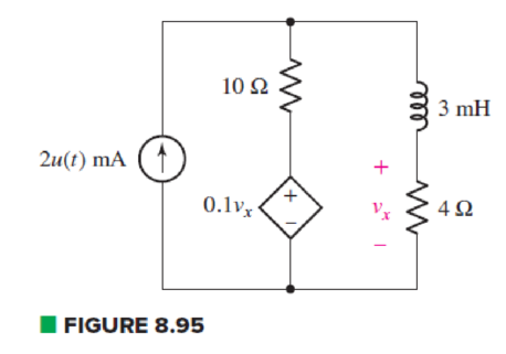
In the circuit of Fig. 8.95, a 3 mF capacitor is accidentally installed instead of the inductor. Unfortunately, that’s not the end of the problems, as it’s later determined that the real capacitor is not really well modeled by an ideal capacitor, and the dielectric has a resistance of 10 kΩ (which should be viewed as connected in parallel to the ideal capacitor). (a) Compute the circuit time constant with and without taking the dielectric resistance into account. By how much does the dielectric change your answer? (b) Calculate vx at t = 200 ms. Does the dielectric resistance affect your answer significantly? Explain.
(a)
Find the value of circuit time constant with and without taking dielectric resistance and explain the change in time constant by dielectric resistance.
Answer to Problem 77E
Value of time constant without dielectric is
Explanation of Solution
Given Data:
Value of capacitor by which the
Value of dielectric resistance is
Formula used:
The expression for resistance is as follows:
Here,
The expression for the circuit time constant is as follows:
Here,
Calculation:
To find equivalent resistance of a circuit seen by the capacitor, open circuit the inductor and replace all independent sources by their internal resistances. That is, replace current source by open circuit.
Circuit contains dependent voltage source. So to find equivalent resistance connect an arbitrary voltage source of
The circuit diagram is redrawn as shown in Figure 1.
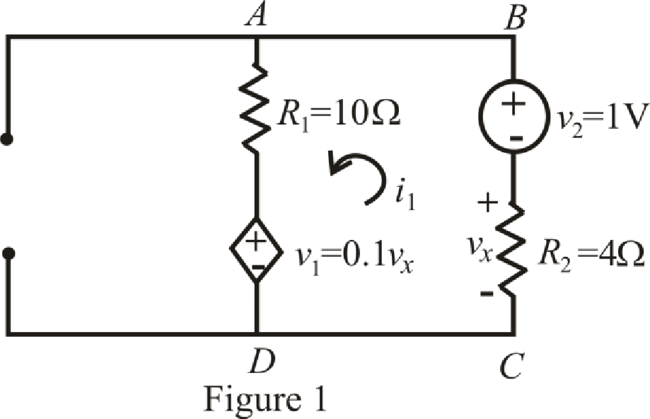
Refer to the redrawn Figure 1.
Circuit is drawn for without dielectric resistor.
The expression for Kirchhoff’s voltage law in mesh
Here,
Substitute
The expression for
Here,
Substitute
Substitute
Rearrange equation (6) for
Simplify for
Substitute
Substitute
So, value of time constant without dielectric is
To find equivalent resistance of a circuit, independent sources are replaced by their internal resistances. Therefore, replace current source by open circuit.
Circuit is containing dependent voltage source. So, to find equivalent resistance connect a voltage source of
The circuit diagram is redrawn as shown in Figure 2.
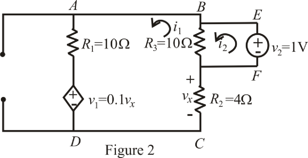
Refer to the redrawn Figure 2:
Circuit is drawn for resistor with dielectric.
The expression for KVL in mesh
Here,
The expression for KVL in mesh
Here,
Substitute
Substitute
Rearrange (10) for
Substitute
Rearrange equation (12) for
Substitute
Rearrange equation (13) for
Simplify for
Substitute
Substitute
So value of time constant with dielectric is
The expression for percentage change in time constant with dielectric resistor is as follows;
Here,
Substitute
Conclusion:
Thus, value of time constant without dielectric is
(b)
Calculate
Answer to Problem 77E
Value of voltage
Explanation of Solution
Given Data:
Value of time
Formula used:
The expression for voltage is as follows:
Here,
The expression for the final response is as follows:
Here,
The expression for current flowing through capacitor is as follows:
Here,
Calculation:
The circuit diagram is redrawn as shown in Figure 3 for
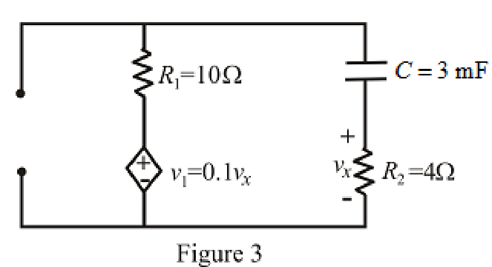
Refer to the redrawn Figure 3:
Circuit is drawn for resistor without dielectric.
As there is no independent source present in the circuit which means voltage across capacitor is also
So, value of
At
Therefore,
So,
The circuit diagram is redrawn as shown in Figure 4 for
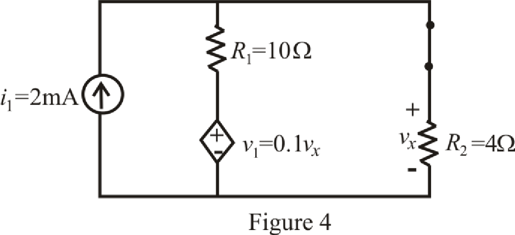
At
So, capacitor behaves as open circuit.
The circuit diagram is redrawn as shown in Figure 5 for
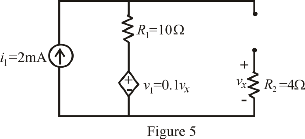
Refer to the redrawn Figure 5:
The expression for voltage
Here,
As capacitor is open circuited, current flowing through resistor
Which means value of voltage
Substitute
The circuit diagram is redrawn as shown in Figure 6 for
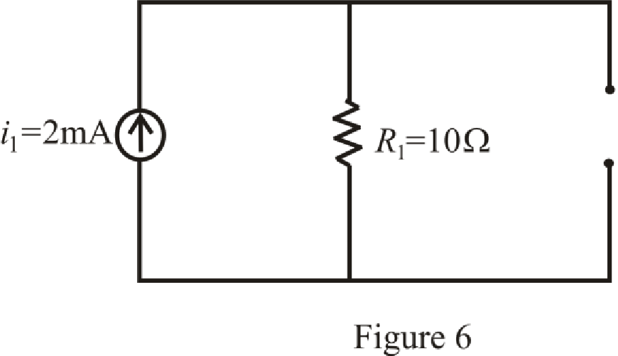
Refer to the redrawn Figure 6:
Substitute
So,
Substitute
Substitute
Substitute
The expression for voltage
Here,
Substitute
So, value of voltage
Circuit is drawn for resistor with dielectric.
The circuit diagram is redrawn as shown in Figure 7 for
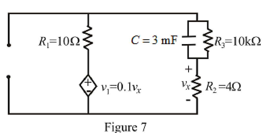
Refer to the redrawn Figure 7:
As there is no independent source present in the circuit which means voltage across capacitor is also
So, value of
At
Therefore,
So,
The circuit diagram is redrawn as shown in Figure 8for
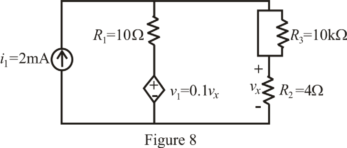
At
So, capacitor behaves as open circuit.
The circuit diagram is redrawn as shown in Figure 9 for
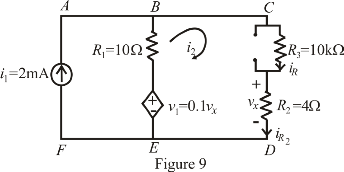
Refer to the redrawn Figure 9:
The expression for KVL in mesh
Here,
Substitute
The expression for voltage
Here,
Substitute
Substitute
Rearrange equation (24) for
Simplify for
Substitute
So,
Substitute
Substitute
Substitute
Substitute
The expression for current
Here,
Substitute
The expression for current
Here,
Substitute
The expression for voltage
Here,
Substitute
So value of voltage
The expression for percentage change in voltage
Here,
Substitute
Conclusion:
Thus, value of voltage
Want to see more full solutions like this?
Chapter 8 Solutions
Loose Leaf for Engineering Circuit Analysis Format: Loose-leaf


- 8. a). What are the values of the inductor voltage and current and the capacitor voltage and current assuming the switch has been closed for a very long time. VL= IL = Vc = Ic= 10 v 1H V₁ 000 502 HI 292 Ic↓ 1F Vcarrow_forwardA capacitor has a capacitance of 0.1 μF with air as the dielectric. If the dielectric material is changed from air to a ceramic material with a dielectric constant of 600, what is the new capacitance? (Note: Neither air nor Ceramic capacitors this large are available.)arrow_forwardA series circuit has a capacitor of 0.25 x 10-0 F, a resistor of 5x 10' 2, and an inductor of 1 H. The initial charge on the capacitor is zero. If a 12-volt battery is connected to the ircuit and the circuit is closed at t = 0, determine the charge on the capacitor at t = 0.001 seconds, at t = 0.01 seconds, and at any time t. Also determine the limiting charge as - 0. Enter the exact answer with a < b. The charge at any time is given by the formula Q (1) = (Ae" + Beb + C) x 10-6 coulombs, where %3D x10-6 coulombs as t→ 0 tound your answers to two decimal places. 20 001) = x10-6 Coulomhsarrow_forward
- 2) An LC circuit is made by attaching a 0.2221 H inductor is connected across a variable capacitor whose capacitance can be varied by turning a knob. a) . At what angle should the knob be set so that the circuit ocillates with a period of 8.000 ms? SuF OµF - 10µF b) What voltage battery do I need to charge up the capacitor to an initial charge of 87.60 µC? (assume the period is set to 8.000 ms) Сарасiance c) What is the maximum current in this LC Circuit? (all numbers 4 sig figs) (assume the initial charge is 87.60 µC)arrow_forwardA capacitor has been connected in series with a resistor to a DC source at t=0. If the capacitor has an initial voltage R$ Vo=2V with same orientation of the source voltage, then the capacitor voltage v.(t) is A (tRC)arrow_forwardFind the equivalent capacitance for the following circuit.arrow_forward
- A circuit having a 120µF capacitor and a 10kN resistance in series is connected across a 230-V dc supply. Determine the final energy (in Joules) stored in the capacitor. Answer:arrow_forwardTwo capacitors of 200 and 800 nF, respectively are connected in parallel. The combination is then connected in series with another two capacitors of C and 600 nF connected in parallel. If the total capacitance of the set-up is 500 nF, determine the capacitance C.arrow_forwardQ8. What is the charge of the second capacitor(C2)? A) 64mc B) 32mc C) 16me D) 48mc E) 24mc C2=8mf] C1=6mf C3-4 mf V=12Varrow_forward
- Determine the equivalent capacitance for the given circuit, where C=1 F. 6 F 4 F 2 F The equivalent capacitance is F.arrow_forwardTRUE or FALSE a. A discontinuous change in the voltage requires an infinite current thus a capacitor resists an abrupt change in the voltage across it. b. The inductor takes power from the circuit when storing energy and delivers power to the circuit when returning previously stored energy.arrow_forwardThe voltage applied to a series RLC circuit is v = 200 sin 200t volts and the resulting current is i = 5 sin (200t + 40degree) amp. The capacitor in series has a value of 30 microfarad. Find the inductance of the circuit in Henry.arrow_forward
 Introductory Circuit Analysis (13th Edition)Electrical EngineeringISBN:9780133923605Author:Robert L. BoylestadPublisher:PEARSON
 Delmar's Standard Textbook Of ElectricityElectrical EngineeringISBN:9781337900348Author:Stephen L. HermanPublisher:Cengage Learning
 Programmable Logic ControllersElectrical EngineeringISBN:9780073373843Author:Frank D. PetruzellaPublisher:McGraw-Hill Education
 Fundamentals of Electric CircuitsElectrical EngineeringISBN:9780078028229Author:Charles K Alexander, Matthew SadikuPublisher:McGraw-Hill Education
 Electric Circuits. (11th Edition)Electrical EngineeringISBN:9780134746968Author:James W. Nilsson, Susan RiedelPublisher:PEARSON
 Engineering ElectromagneticsElectrical EngineeringISBN:9780078028151Author:Hayt, William H. (william Hart), Jr, BUCK, John A.Publisher:Mcgraw-hill Education,