
Concept explainers
Videos
Design a two−pole low−pass Butterworth filter with a bandwidth of2.5 kHz. The largest capacitor value to be used is 50 pF. (Ans. Set
The design parameters of a low-pass Butterworth filter.
Answer to Problem 15.1EP
The design parameters are:
Explanation of Solution
Given Information:
Bandwidth of low-pass Butterworth filter is
Value of largest capacitor is 50 pF.
Calculation:
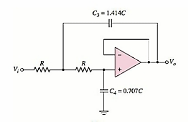
A general low-pass Butterworth circuit is shown below.
Consider
The relation between
So, the value of capacitor
dB frequency or bandwidth of the circuit is
Substituting the values,
The value of capacitor C is
So, the value of resistance R, from equation (1) is
Want to see more full solutions like this?
Chapter 15 Solutions
Microelectronics: Circuit Analysis and Design


- Design a series RLC bandpass filter as shown in the figure with lower cut-off frequency f = 400 Hz and bandwidth B = 9600 Hz %3D a) Determine the higher cut-off frequency f# b) Determine the center or resonant frequency fo in Hz and wo in rad/s and calculate the quality factor Q c) Choose C = 2 nF and find the values of R and L to meet the design specifications C No V: Oarrow_forwardb) Find the transfer function VN, of the circuit in Figure Q3 (c). Show that the circuit is a lowpass filter. 1 H ele + 0.25 Q 1F= 'o Figure 03(c)arrow_forward(B2) The magnitude characteristic of this filter is equiripple in the passband and monotonic in the stopband.arrow_forward
- Design a low pass active filter with a dc gain of 4 and a comer frequency of 500Hz ?arrow_forwardCh#2 Active Filters Find the transfer function T(s) for the circuit shown in figure below. CAI RAI RBI o Vo Vin CB1 R1 R2arrow_forwardI want the answer in detail and as quickly as possible please Q/ Using capacitors and resistors, design A - (band-pass filters) with Fl=105HZ and Fh=115HZ. B - Design (band-pass filters) with FI = 215HZ and Fh = 225HZ.arrow_forward
- Passive Band Pass Filter H.W) What is the central bandpass frequency (fo) expressed in terms of circuit component values. + R + Vin L. C Vout 1 fo= 2nVLCarrow_forwardCalculate the cutoff frequency for the opamp Sallen-Key 2nd order highpass filterarrow_forwardWhich of the following statement is true for the figure shown below. O LTI system RC low-pass filter - labAlive O RC low-pass fiter- Properties File Run Simulation Help Cutoff frequency > 320 MHz V O Signal Generator - Properties Amplitude Frequency < Output 1.73 H ic) 45.0 MHz On Waveform Sine The voltage at the output is higher compared to the initial voltage at the input O b. The output voltage cannot be determine since the input frequency is too high compare to cutoff frequency O. The voltage at the output is lower compared to the initial voltage at the input O d. The voltage at the output is equal to the initial voltage at the inputarrow_forward
- Design a series RLC bandpass filter as shown in the figure with lower cut-off frequency f = 400 Hz and bandwidth B = 9600 Hz a) Determine the higher cut-off frequency fH b) Determine the center or resonant frequency fo in Hz and wo in rad/s and calculate the quality factor Q c) Choose C = 2 nF and find the values of R and L to meet the design specifications C R Noarrow_forwardHW: Determine Zin, Zo and the small-signal voltage gain. P type C₁ C₂ Vo D Vin Rs RD RL SINT 4k 2k 4k Zin -5V Zo +5V = kp 1mA/V2 Vr = -0.8V λ=0 Bobin painleido XL=SL = jwL Frequency Response Sm= 2 kp (VSG₂Q +VT) rd = 1 A IDQ ID= kp (VSC₂+V+) ² notion Xc = Copacite 1 (WC 345arrow_forwardThe input to this band pass filter is an Ac signal with an aplitude of 2V and frequency of 100KHz, R=100, L=0.5nH, C=0.5nF. Determine the following: a.) Vout b.) foarrow_forward
 Introductory Circuit Analysis (13th Edition)Electrical EngineeringISBN:9780133923605Author:Robert L. BoylestadPublisher:PEARSON
 Delmar's Standard Textbook Of ElectricityElectrical EngineeringISBN:9781337900348Author:Stephen L. HermanPublisher:Cengage Learning
 Programmable Logic ControllersElectrical EngineeringISBN:9780073373843Author:Frank D. PetruzellaPublisher:McGraw-Hill Education
 Fundamentals of Electric CircuitsElectrical EngineeringISBN:9780078028229Author:Charles K Alexander, Matthew SadikuPublisher:McGraw-Hill Education
 Electric Circuits. (11th Edition)Electrical EngineeringISBN:9780134746968Author:James W. Nilsson, Susan RiedelPublisher:PEARSON
 Engineering ElectromagneticsElectrical EngineeringISBN:9780078028151Author:Hayt, William H. (william Hart), Jr, BUCK, John A.Publisher:Mcgraw-hill Education,